Sony XR-1790 (serv.man3) Service Manual ▷ View online
SERVICE MANUAL
XR-1790
US Model
Canadian Model
E Model
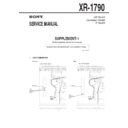
SUPPLEMENT-1
File this supplement with the service manual.
Subject: Tuner unit Modification (US, Canadian model)
(ENG-99004)
1.
DISCRIMINATION
Former:
New:
– SET UPPER VIEW –
TU100
Two
adjustment
holes
adjustment
holes
CN901
TU100
One
adjustment
hole
adjustment
hole
CN901
– SET UPPER VIEW –
– 2 –
2.
ELECTRICAL ADJUSTMENTS
• AM section adjustment is done automatically in this set.
Cautions during repair
When the tuner unit is defective, replace it by a new one be-
cause its internal block is difficult to repair.
cause its internal block is difficult to repair.
Note:
Adjust the tuner section in the sequence shown below.
1. FM Auto Scan/Stop Level Adjustment
2. FM Stereo Separation Adjustment
2. FM Stereo Separation Adjustment
FM Auto Scan/Stop Level Adjustment
Setting:
[TUNER]
button: FM 1
Procedure:
1. Tune the set to 97.9 MHz.
2. Connect the digital voltmeter to TP2 (SD) on MAIN board.
3. Adjust RV1 on TU100 so that the reading on the digital volt-
1. Tune the set to 97.9 MHz.
2. Connect the digital voltmeter to TP2 (SD) on MAIN board.
3. Adjust RV1 on TU100 so that the reading on the digital volt-
meter changes point from low to high.
Adjustment Location: See page 3.
TUNER SECTION
0 dB=1 µV
+
–
–
TP2 (SD)
MAIN board
digital
voltmeter
voltmeter
FM Stereo Separation Adjustment
Setting:
[TUNER]
button: FM1
Procedure:
L-CH Stereo separation: A-B
R-CH Stereo separation: C-D
The separations of both channels should be equal.
R-CH Stereo separation: C-D
The separations of both channels should be equal.
Specification: Separation more than 28 dB
Adjustment Location: See page 3.
FM Stereo
Level meter
Level meter
signal generator
connection
reading (dB)
output channel
L-CH
L-CH
A
B
R-CH
L-CH
Adjust RV2 on TU100
for minimum reading.
R-CH
R-CH
C
D
L-CH
R-CH
Adjust RV2 on TU100
for minimum reading.
FM RF signal
generator
generator
Carrier frequency: 97.9 MHz
Output level: 22
Output level: 22
±
5 dB
Mode: mono
Modulation: 1 kHz, 22.5 kHz deviation (30%)
Modulation: 1 kHz, 22.5 kHz deviation (30%)
0.01
µ
F
set
antenna jack (CN900)
FM RF signal
generator
Carrier frequency : 97.9 MHz
Output level
Output level
: 74 dB
Mode
: stereo
Modulation
: main: 1 kHz, 33.75 kHz deviation (45%)
sub: 1 kHz, 33.75 kHz deviation (45%)
19 kHz pilot: 7.5 kHz deviation (10%)
sub: 1 kHz, 33.75 kHz deviation (45%)
19 kHz pilot: 7.5 kHz deviation (10%)
0.01
µ
F
set
antenna jack (CN900)
+
–
–
speaker out terminal
level meter
4
Ω
– 3 –
Adjustment Location:
TP2 (SD)
– SET BOTTOM VIEW –
– SET UPPER VIEW –
TU100
CN901
– TU100 (Component Side) –
RV1 FM Auto Scan/Stop Level Adjustment
RV2 FM Stereo Separation Adjustment
– 4 –
3.
DIAGRAMS
3-1.
NOTES FOR PRINTED WIRING BOARD AND SCHEMATIC DIAGRAM
Note on Schematic Diagram:
• All capacitors are in µF unless otherwise noted. pF: µµF
• All capacitors are in µF unless otherwise noted. pF: µµF
50 WV or less are not indicated except for electrolytics
and tantalums.
and tantalums.
• All resistors are in
Ω
and
1
/
4
W or less unless otherwise
specified.
•
¢
: internal component.
•
2
: nonflammable resistor.
•
C
: panel designation.
•
U
: B+ Line.
• Power voltage is dc 14.4V and fed with regulated dc power
supply from ACC and BATT cords.
• Voltages and waveforms are dc with respect to ground
under no-signal (detuned) conditions.
no mark : FM
(
no mark : FM
(
) : AM
[
] : TAPE PLAYBACK
• Voltages are taken with a VOM (Input impedance 10 M
Ω
).
Voltage variations may be noted due to normal produc-
tion tolerances.
tion tolerances.
• Waveforms are taken with a oscilloscope.
Voltage variations may be noted due to normal produc-
tion tolerances.
tion tolerances.
• Circled numbers refer to waveforms.
• Signal path.
• Signal path.
F
: FM
f
: AM
E
: TAPE PLAYBACK
Note on Printed Wiring Board:
• X
: parts extracted from the component side.
• Y
: parts extracted from the conductor side.
•
¢
: internal component.
• b
: Pattern from the side which enables seeing.

