 <, div> service manual" title="View screenshot" />
Sony MG101_x000D_
< / div> Service Manual ▷ View online
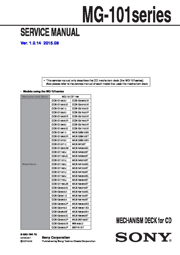
SERVICE MANUAL
Sony Corporation
Published by Sony Techno Create Corporation
MG-101series
9-893-794-15
2015I33-1
©
2015.09
Ver. 1.0.14 2015.09
MECHANISM DECK for CD
• This service manual only describes the CD mechanism deck (the MG-101series).
Also please refer to the service manual of each model that uses this mechanism deck.
•
Models using the MG-101series
Mechanism deck Name
MG-101CF-188
Model Name
CDX-G1000U
CDX-G3050UV
CDX-G1000UE
CDX-G3070UV
CDX-G1001U
CDX-G3100UE
CDX-G1002U
CDX-G3100UP
CDX-G1003ER
CDX-G3100UV
CDX-G1003UR
CDX-G3150UP
CDX-G1050U
CDX-G3150UV
CDX-G1050UE
CDX-G3170UV
CDX-G1051U
MEX-GS610BE
CDX-G1053UR
MEX-GS610BT
CDX-G1070U
MEX-GS810BH
CDX-G1071U
MEX-M70BT
CDX-G1080UM
MEX-N4000BE
CDX-G1100U
MEX-N4000BT
CDX-G1100UE
MEX-N4050BT
CDX-G1101U
MEX-N4070BT
CDX-G1102U
MEX-N4100BE
CDX-G1150U
MEX-N4100BT
CDX-G1151U
MEX-N4150BT
CDX-G1152U
MEX-N5000BE
CDX-G1170U
MEX-N5000BT
CDX-G1180UM
MEX-N5050BT
CDX-G2000UE
MEX-N5070BT
CDX-G2000UI
MEX-N5100BE
CDX-G2001UI
MEX-N5100BT
CDX-G2050UI
MEX-N5150BT
CDX-G2050UP
MEX-N6000BD
CDX-G2070UI
MEX-N6001BD
CDX-G2080IM
MEX-N6000BH
CDX-G3000UE
MEX-N6050BT
CDX-G3000UP
MEX-XB100BT
CDX-G3000UV
WX-800UI
CDX-G3050UP
XSP-N1BT
MG-101series
2
NOTES ON CHIP COMPONENT REPLACEMENT
•
Never reuse a disconnected chip component.
•
Notice that the minus side of a tantalum capacitor may be dam-
aged by heat.
FLEXIBLE CIRCUIT BOARD REPAIRING
•
Keep the temperature of soldering iron around 270 °C during
repairing.
•
Do not touch the soldering iron on the same conductor of the
circuit board (within 3 times).
•
Be careful not to apply force on the conductor when soldering
or unsoldering.
CAUTION
Use of controls or adjustments or performance of procedures
other than those specifi ed herein may result in hazardous radia-
tion exposure.
SECTION 1
SERVICING NOTES
NOTES ON HANDLING THE OPTICAL PICK-UP
BLOCK OR BASE UNIT
The laser diode in the optical pick-up block may suffer electro-
static break-down because of the potential difference generated by
the charged electrostatic load, etc. on clothing and the human body.
During repair, pay attention to electrostatic break-down and also
use the procedure in the printed matter which is included in the
repair parts.
The fl exible board is easily damaged and should be handled with
care.
NOTES ON LASER DIODE EMISSION CHECK
Never look into the laser diode emission from right above when
checking it for adjustment. It is feared that you will lose your sight.
If the optical pick-up block is defective, please replace the whole
optical pick-up block.
Never turn the semi-fi xed resistor located at the side of optical
pick-up block.
optical pick-up
semi-fixed resistor
NOTE OF REPLACING THE SERVO BOARD
When the SERVO board is defective, exchange the complete mount-
ed board.
NOTE OF REPLACING THE SENSOR BOARD
When the SENSOR board is defective, exchange the MECHANI-
CAL BLOCK (11CA2) ASSY (Ref. No. CDM1).
SAFETY-RELATED COMPONENT WARNING!
COMPONENTS IDENTIFIED BY MARK 0 OR DOTTED LINE
WITH MARK 0 ON THE SCHEMATIC DIAGRAMS AND IN
THE PARTS LIST ARE CRITICAL TO SAFE OPERATION.
REPLACE THESE COMPONENTS WITH SONY PARTS
WHOSE PART NUMBERS APPEAR AS SHOWN IN THIS
MANUAL OR IN SUPPLEMENTS PUBLISHED BY SONY.
ATTENTION AU COMPOSANT AYANT RAPPORT
À LA SÉCURITÉ!
LES COMPOSANTS IDENTIFIÉS PAR UNE MARQUE 0 SUR
LES DIAGRAMMES SCHÉMATIQUES ET LA LISTE DES
PIÈCES SONT CRITIQUES POUR LA SÉCURITÉ DE FONC-
TIONNEMENT. NE REMPLACER CES COMPOSANTS QUE
PAR DES PIÈCES SONY DONT LES NUMÉROS SONT DON-
NÉS DANS CE MANUEL OU DANS LES SUPPLÉMENTS
PUBLIÉS PAR SONY.
US and Canadian models:
CAUTION
The use of optical instruments with this product
will increase eye hazard.
MG-101series
3
SECTION 2
DISASSEMBLY
• This set can be disassembled in the order shown below.
2-1. DISASSEMBLY FLOW
SET
2-2. SERVO
BOARD
(Page
4)
2-3. CHASSIS (T) SUB ASSY
(Page
5)
2-4. ROLLER ARM ASSY
(Page
6)
2-5. TENSION SPRING (KF)
(Page
6)
2-6. CHASSIS (OP) BLOCK-1
(Page
7)
2-7. CHASSIS (OP) BLOCK-2
(Page
8)
2-8.
LE MOTOR BLOCK
(Page
8)
2-9. OPTICAL PICK-UP BLOCK
(Page
9)
2-10. OPTICAL PICK-UP (OP1)
(Page
9)
MG-101series
4
Note:
Follow the disassembly procedure in the numerical order given.
2-2. SERVO BOARD
–
Bottom view
–
OK
NG
NG
• Optical pick-up flexible board setting
• Wire setting
< Fig. A >
to LE motor
to SENSOR
board
6 claw
2 Remove two solders.
(See
Fig.
A)
2 Remove three solders.
(See
Fig.
A)
2 Remove six solders.
(See
Fig.
A)
A
A
[white]
[red]
[red]
[gray]
[white]
[black]
[black]
[yellow]
[red]
[orange]
[blue]
OK
NG
• Wire setting
7 SERVO board
6 claw
5 two toothed lock screws
(M1.7
u 2.5)
Optical pick-up flexible board is
riding on the SERVO board.
Optical pick-up flexible board is
under the SERVO board.
1 adhesive tape
(ST-854GH)
1 adhesive tape
(ST-854GH)
adhesive tape (ST-854GH)
4 optical pick-up
flexible
board
(CN101)
SERVO board
adhesive tape (ST-854GH)
Wire passes through
the over of the hole.
• Wire setting
SERVO board
claw
adhesive tape
(ST-854GH)
adhesive tape
(ST-854GH)
from chassis (OP) block
to chassis
(OP) block
from LE motor
from SENSOR
board
3 Unlock the connector.
SERVICE MANUAL
Sony Corporation
Published by Sony Techno Create Corporation
MG-101series
9-893-794-15
2015I33-1
©
2015.09
Ver. 1.0.14 2015.09
MECHANISM DECK for CD
• This service manual only describes the CD mechanism deck (the MG-101series).
Also please refer to the service manual of each model that uses this mechanism deck.
Also please refer to the service manual of each model that uses this mechanism deck.
•
Models using the MG-101series
Mechanism deck Name
MG-101CF-188
Model Name
CDX-G1000U
CDX-G3050UV
CDX-G1000UE
CDX-G3070UV
CDX-G1001U
CDX-G3100UE
CDX-G1002U
CDX-G3100UP
CDX-G1003ER
CDX-G3100UV
CDX-G1003UR
CDX-G3150UP
CDX-G1050U
CDX-G3150UV
CDX-G1050UE
CDX-G3170UV
CDX-G1051U
MEX-GS610BE
CDX-G1053UR
MEX-GS610BT
CDX-G1070U
MEX-GS810BH
CDX-G1071U
MEX-M70BT
CDX-G1080UM
MEX-N4000BE
CDX-G1100U
MEX-N4000BT
CDX-G1100UE
MEX-N4050BT
CDX-G1101U
MEX-N4070BT
CDX-G1102U
MEX-N4100BE
CDX-G1150U
MEX-N4100BT
CDX-G1151U
MEX-N4150BT
CDX-G1152U
MEX-N5000BE
CDX-G1170U
MEX-N5000BT
CDX-G1180UM
MEX-N5050BT
CDX-G2000UE
MEX-N5070BT
CDX-G2000UI
MEX-N5100BE
CDX-G2001UI
MEX-N5100BT
CDX-G2050UI
MEX-N5150BT
CDX-G2050UP
MEX-N6000BD
CDX-G2070UI
MEX-N6001BD
CDX-G2080IM
MEX-N6000BH
CDX-G3000UE
MEX-N6050BT
CDX-G3000UP
MEX-XB100BT
CDX-G3000UV
WX-800UI
CDX-G3050UP
XSP-N1BT
MG-101series
2
NOTES ON CHIP COMPONENT REPLACEMENT
•
•
Never reuse a disconnected chip component.
•
Notice that the minus side of a tantalum capacitor may be dam-
aged by heat.
aged by heat.
FLEXIBLE CIRCUIT BOARD REPAIRING
•
•
Keep the temperature of soldering iron around 270 °C during
repairing.
repairing.
•
Do not touch the soldering iron on the same conductor of the
circuit board (within 3 times).
circuit board (within 3 times).
•
Be careful not to apply force on the conductor when soldering
or unsoldering.
or unsoldering.
CAUTION
Use of controls or adjustments or performance of procedures
other than those specifi ed herein may result in hazardous radia-
tion exposure.
Use of controls or adjustments or performance of procedures
other than those specifi ed herein may result in hazardous radia-
tion exposure.
SECTION 1
SERVICING NOTES
NOTES ON HANDLING THE OPTICAL PICK-UP
BLOCK OR BASE UNIT
BLOCK OR BASE UNIT
The laser diode in the optical pick-up block may suffer electro-
static break-down because of the potential difference generated by
the charged electrostatic load, etc. on clothing and the human body.
During repair, pay attention to electrostatic break-down and also
use the procedure in the printed matter which is included in the
repair parts.
The fl exible board is easily damaged and should be handled with
care.
NOTES ON LASER DIODE EMISSION CHECK
Never look into the laser diode emission from right above when
checking it for adjustment. It is feared that you will lose your sight.
Never look into the laser diode emission from right above when
checking it for adjustment. It is feared that you will lose your sight.
If the optical pick-up block is defective, please replace the whole
optical pick-up block.
Never turn the semi-fi xed resistor located at the side of optical
pick-up block.
optical pick-up block.
Never turn the semi-fi xed resistor located at the side of optical
pick-up block.
optical pick-up
semi-fixed resistor
NOTE OF REPLACING THE SERVO BOARD
When the SERVO board is defective, exchange the complete mount-
ed board.
When the SERVO board is defective, exchange the complete mount-
ed board.
NOTE OF REPLACING THE SENSOR BOARD
When the SENSOR board is defective, exchange the MECHANI-
CAL BLOCK (11CA2) ASSY (Ref. No. CDM1).
When the SENSOR board is defective, exchange the MECHANI-
CAL BLOCK (11CA2) ASSY (Ref. No. CDM1).
SAFETY-RELATED COMPONENT WARNING!
COMPONENTS IDENTIFIED BY MARK 0 OR DOTTED LINE
WITH MARK 0 ON THE SCHEMATIC DIAGRAMS AND IN
THE PARTS LIST ARE CRITICAL TO SAFE OPERATION.
REPLACE THESE COMPONENTS WITH SONY PARTS
WITH MARK 0 ON THE SCHEMATIC DIAGRAMS AND IN
THE PARTS LIST ARE CRITICAL TO SAFE OPERATION.
REPLACE THESE COMPONENTS WITH SONY PARTS
WHOSE PART NUMBERS APPEAR AS SHOWN IN THIS
MANUAL OR IN SUPPLEMENTS PUBLISHED BY SONY.
MANUAL OR IN SUPPLEMENTS PUBLISHED BY SONY.
ATTENTION AU COMPOSANT AYANT RAPPORT
À LA SÉCURITÉ!
LES COMPOSANTS IDENTIFIÉS PAR UNE MARQUE 0 SUR
LES DIAGRAMMES SCHÉMATIQUES ET LA LISTE DES
PIÈCES SONT CRITIQUES POUR LA SÉCURITÉ DE FONC-
TIONNEMENT. NE REMPLACER CES COMPOSANTS QUE
PAR DES PIÈCES SONY DONT LES NUMÉROS SONT DON-
NÉS DANS CE MANUEL OU DANS LES SUPPLÉMENTS
PUBLIÉS PAR SONY.
LES DIAGRAMMES SCHÉMATIQUES ET LA LISTE DES
PIÈCES SONT CRITIQUES POUR LA SÉCURITÉ DE FONC-
TIONNEMENT. NE REMPLACER CES COMPOSANTS QUE
PAR DES PIÈCES SONY DONT LES NUMÉROS SONT DON-
NÉS DANS CE MANUEL OU DANS LES SUPPLÉMENTS
PUBLIÉS PAR SONY.
US and Canadian models:
CAUTION
The use of optical instruments with this product
will increase eye hazard.
will increase eye hazard.
MG-101series
3
SECTION 2
DISASSEMBLY
• This set can be disassembled in the order shown below.
2-1. DISASSEMBLY FLOW
SET
2-2. SERVO
BOARD
(Page
4)
2-3. CHASSIS (T) SUB ASSY
(Page
(Page
5)
2-4. ROLLER ARM ASSY
(Page
(Page
6)
2-5. TENSION SPRING (KF)
(Page
(Page
6)
2-6. CHASSIS (OP) BLOCK-1
(Page
(Page
7)
2-7. CHASSIS (OP) BLOCK-2
(Page
(Page
8)
2-8.
LE MOTOR BLOCK
(Page
8)
2-9. OPTICAL PICK-UP BLOCK
(Page
(Page
9)
2-10. OPTICAL PICK-UP (OP1)
(Page
(Page
9)
MG-101series
4
Note:
Follow the disassembly procedure in the numerical order given.
2-2. SERVO BOARD
–
Bottom view
–
OK
NG
NG
• Optical pick-up flexible board setting
• Wire setting
< Fig. A >
to LE motor
to SENSOR
board
board
6 claw
2 Remove two solders.
(See
Fig.
A)
2 Remove three solders.
(See
Fig.
A)
2 Remove six solders.
(See
Fig.
A)
A
A
[white]
[red]
[red]
[gray]
[white]
[black]
[black]
[yellow]
[red]
[orange]
[blue]
OK
NG
• Wire setting
7 SERVO board
6 claw
5 two toothed lock screws
(M1.7
u 2.5)
Optical pick-up flexible board is
riding on the SERVO board.
riding on the SERVO board.
Optical pick-up flexible board is
under the SERVO board.
under the SERVO board.
1 adhesive tape
(ST-854GH)
1 adhesive tape
(ST-854GH)
adhesive tape (ST-854GH)
4 optical pick-up
flexible
board
(CN101)
SERVO board
adhesive tape (ST-854GH)
Wire passes through
the over of the hole.
the over of the hole.
• Wire setting
SERVO board
claw
adhesive tape
(ST-854GH)
(ST-854GH)
adhesive tape
(ST-854GH)
(ST-854GH)
from chassis (OP) block
to chassis
(OP) block
(OP) block
from LE motor
from SENSOR
board
board
3 Unlock the connector.
 <, div> (serv.man2) Service Manual" title="View file" />