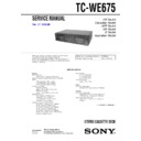
Sony TC-WE675 (serv.man2) Service Manual ▷ View online
3
TC-WE675
PARTS No.
MODEL
4-232-414-0s
US model
4-232-414-1s
CND model
4-232-414-2s
AEP model
4-232-414-3s
UK model
4-232-414-4s
SP model
4-232-414-5s
AUS model
MODEL IDENTIFICATION
–Back panel–
Part No.
• Abbreviation
CND : Canadian model
SP
SP
: Singapore model
AUS : Australian model
TABLE OF CONTENTS
1. GENERAL
.......................................................................... 4
2. DISASSEMBLY
2-1. Case ...................................................................................... 5
2-2. Front Panel Assy ................................................................... 5
2-3. Cassette Lid Assy (Deck A/B) .............................................. 6
2-4. Mechanism Deck Assy (Deck A/B) ...................................... 6
2-2. Front Panel Assy ................................................................... 5
2-3. Cassette Lid Assy (Deck A/B) .............................................. 6
2-4. Mechanism Deck Assy (Deck A/B) ...................................... 6
3. SERVICE MODE
.............................................................. 7
4. MECHANICAL ADJUSTMENTS
................................. 8
5. ELECTRICAL ADJUSTMENTS
................................. 8
6. DIAGRAMS
6-1. Circuit Boards Location ...................................................... 12
6-2. Printed Wiring Board – MAIN Section – ........................... 14
6-3. Schematic Diagram – MAIN (1/4) Section – ..................... 15
6-4. Schematic Diagram – MAIN (2/4) Section – ..................... 16
6-5. Schematic Diagram – MAIN (3/4) Section – ..................... 17
6-6. Schematic Diagram – MAIN (4/4) Section – ..................... 18
6-7. Printed Wiring Board – DECK Section – ........................... 19
6-8. Schematic Diagram – DECK Section – .............................. 19
6-9. Schematic Diagram – LEAF SW Section – ........................ 20
6-10. Printed Wiring Board – LEAF SW Section – ................... 21
6-11. Schematic Diagram – PANEL Section – ........................... 22
6-12. Printed Wiring Board – PANEL Section – ........................ 23
6-13. Schematic Diagram – POWER Section – ......................... 24
6-14. Printed Wiring Board – POWER Section – ...................... 25
6-15. IC PIN FUNCTION .......................................................... 26
7. EXPLODED VIEWS
7-1. Case Section ........................................................................ 27
7-2. Chassis Section ................................................................... 28
7-3. Cassette Holder Section ...................................................... 29
7-4. Front Panel Section ............................................................. 30
7-5. Tape Mechanism Section .................................................... 31
8. ELECTRICAL PARTS LIST
........................................ 32
4
TC-WE675
SECTION 1
GENERAL
Front Panel
Location of Parts and Controls
1
POWER button
2
RESET (Deck A) button
3
MEMORY (Deck A) button
4
RESET (Deck B) button
5
MEMORY (Deck B) button
6
AUTO REC LEVEL indicator
7
REC LEVEL knob
8
FADER button
9
ARL button
0
SYNCHRO button
qa
PHONES jack
qs
HIGH/NOMAL button
qd
A+B REC button
qf
DECK B button
qg
DECK A button
qh
(AMS) M (Deck B) button
qj
m (AMS) (Deck B) button
qk
H (Deck B) button
ql
h (Deck B) button
w;
REC z (Deck B) button
wa
A (Eject) (Deck B) button
ws
REC MUTING W (Deck B) button
wd
PAUSE X (Deck B) button
wf
x (Deck B) button
wg
DOLBY NR B/C switch
wh
DOLBY NR OFF/ON FILTER
wj
H/FRONT (Deck A) button
wk
h/BACK (Deck A) button
wl
REC z (Deck A) button
e;
REC MUTING W (Deck A) button
ea
A (Eject) (Deck A) button
es
PAUSE X (Deck A) button
ed
x/CLEAR (Deck A) button
ef
(AMS) M (Deck A) button RMS +
eg
m (AMS) (Deck A) button RMS –
eh
DISPLAY button
ej
CHECK button
ek
SET button
el
RMS/START button
r;
PITCH CONTROL knob
ra
PITCH CONTROL button
rs
DIRECTION switch
• AMS is the abbreviation for Automatic Music Sensor.
1
2 3
4 5
6 7
ra
rs
r;
wd
wl
e;
ws w; ql qk qj
qf
qg
qd qs
qh
eg ef
wf
wj
wk
wa
ea
ed
9
0
qa
8
wg
es
wh
ek
el
ej eh
5
TC-WE675
SECTION 2
DISASSEMBLY
Note : Follow the disassembly procedure in the numerical order given.
2-1. CASE
2-2. FRONT PANEL ASSY
1
screw
(BVTT 3x6)
2
two screws
(case 3 TP2)
3
two screws
(case 3 TP2)
4
case
qs
screw
(BVTP 3x8)
qf
screw
(BVTP 3x8)
qd
screw
(BVTP 3x8)
qg
two screws
(BVTT 3x6)
qj
claw
qh
claw
qk
front panel assy
8
CN301
7
CN401
2
CN807
1
CN5802
3
CN803
4
CNA806
5
flat type wire
(Deck A)
9
CN002
6
flat type wire
(Deck B)
0
screw
(BVTP 3x8)
qa
wire
Set
Case
Front Panel Assy
Cassette Lid Assy (Deck A/B)
Mechanism Deck Assy (Deck A/B)
• The equipment can be removed using the following procedure.
6
TC-WE675
2-3. CASSETTE LID ASSY (DECK A/B)
2-4. MECHANISM DECK ASSY (DECK A/B)
2
four claws
1
Push the EJECT button.
3
cassette lid assy
1
two screws
(BVTP 2.6x8)
3
mechanism deck assy
2
two screws
(BVTP 2.6x8)


