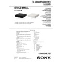
Sony TA-SA500WR / TA-SA600WR / TA-SA700WR Service Manual ▷ View online
TA-SA500WR/SA600WR/SA700WR
7
2-3. FRONT PANEL ASSY
2-4. WLK6-MAIN BOARD
Ver. 1.3
1 wire (flat type)
(26 core) (CN301)
2 two claws
3 claw
4 front panel assy
3 claw
1 Wire is removed
from the pin, wire.
2 CN501 (4P)
9 WLK6-MAIN board
4 CN101
(7P)
(7P)
5 two screws
(+BV3
(+BV3
(3-CR))
7 four screws
(+BV3
(+BV3
(3-CR))
8 one screw
(+BV3
(+BV3
(3-CR))
6 heatsink
3 Remove the cable from the hook.
(SA600WR)
(SA600WR)
front side
pin, wire
WLK6-MAIN board
REGULATOR, SWITCHING
:LUHVHWWLQJ
TA-SA500WR/SA600WR/SA700WR
8
2-5. SWITCHING REGULATOR
Ver. 1.3
1 CN1 (2P)
4 REGULATOR, SWITCHING
2 four screws
(+BV3
(+BV3
(3-CR))
3 holder, PC board
TA-SA500WR/SA600WR/SA700WR
9
SECTION 3
TEST MODE
COLD RESET
Note:
The main unit corresponding to the surround amplifier (TA-
SA500WR or TA-SA600WR or TA-SA700WR), and the remote com-
mander corresponding to the main unit are necessary to execute this mode.
mander corresponding to the main unit are necessary to execute this mode.
Procedure:
1. Connect the AC power cord of the main unit.
2. Press
1. Connect the AC power cord of the main unit.
2. Press
[\/1] button on the main unit to turn the system on.
"/1
[ ] button
3. Connect the AC power cord of the surround amplifier (TA-
SA500WR or TA-SA600WR or TA-SA700WR).
4. When wireless transmission is activated, the [LINK/STAND-
BY] indicator of the surround amplifier (TA-SA500WR or TA-
SA600WR or TA-SA700WR) turns green.
SA600WR or TA-SA700WR) turns green.
Note:
Refer to the operating instructions when the [LINK/STAND-
BY] indicator of the surround amplifier (TA-SA500WR or
TA-SA600WR or TA-SA700WR) doesn’t light.
TA-SA600WR or TA-SA700WR) doesn’t light.
[LINK/STANDBY] indicator
5. Press the button in order of the [
x
]
[DISPLAY]
[RETURN]
[M] on the remote commander corresponding
to main unit aiming at the main unit.
6. Confirm the [LINK/STANDBY] indicator of the surround am-
plifier (TA-SA500WR or TA-SA600WR or TA-SA700WR) is
orange lighting after step 5 is executed.
orange lighting after step 5 is executed.
7. The AC power cord of the surround amplifier (TA-SA500WR
or TA-SA600WR or TA-SA700WR) is pulled out to turn off
the system.
the system.
Note:
Please insert it after confirming the [LINK/STANDBY]
indicator of the surround amplifier (TA-SA500WR or TA-
SA600WR or TA-SA700WR) has been turned off when you
insert the AC power cord again.
indicator of the surround amplifier (TA-SA500WR or TA-
SA600WR or TA-SA700WR) has been turned off when you
insert the AC power cord again.
TA-SA500WR/SA600WR/SA700WR
10
SECTION 4
DIAGRAMS
For Schematic Diagrams.
Note:
• All capacitors are in
• All capacitors are in
μF unless otherwise noted. (p: pF) 50
WV or less are not indicated except for electrolytics and
tantalums.
tantalums.
• All resistors are in
Ω and 1/4 W or less unless otherwise
specified.
• f
: internal component.
•
2 : Nonflammable resistor.
•
5 : Fusible resistor.
•
C : panel designation.
THIS NOTE IS COMMON FOR PRINTED WIRING BOARDS AND SCHEMATIC DIAGRAMS.
(In addition to this, the necessary note is printed in each block.)
(In addition to this, the necessary note is printed in each block.)
•
A : B+ Line.
• Voltages and waveforms are dc with respect to ground
under no-signal conditions.
no mark : POWER ON
• Voltages are taken with VOM (Input impedance 10 M
• Voltages are taken with VOM (Input impedance 10 M
).
Voltage variations may be noted due to normal production
tolerances.
• Waveforms are taken with a oscilloscope.
Voltage variations may be noted due to normal production
Voltage variations may be noted due to normal production
tolerances.
• Circled numbers refer to waveforms.
• Signal path.
F :
AUDIO
• Abbreviation
AR
AR
:
Argentina
model
AUS :
Australian
model
CH
:
Chinese
model
CND :
Canadian
model
E3
: 240 V AC area in E model
E12
: 220 – 240 V AC area in E model
E32
: 110 – 240 V AC area in E model
E51
: Chilean and Peruvian models
EA
:
Saudi
Arabia
model
MX
:
Mexican
model
MX6 :
Latin-American
model
PX
:
PX
model
RU
:
Russian
model
SP
:
Singapore
model
TH
:
Thai
model
TW
:
Taiwan
model
For Printed Wiring Boards.
Note:
•
•
X : Parts extracted from the component side.
•
Y : Parts extracted from the conductor side.
• f
: Internal component.
•
: Pattern from the side which enables seeing.
(The other layers' patterns are not indicated.)
Caution:
Pattern face side:
(Conductor Side)
Parts face side:
(Component Side)
Pattern face side:
(Conductor Side)
Parts face side:
(Component Side)
Parts on the pattern face side seen
from the pattern face are indicated.
Parts on the parts face side seen from
the parts face are indicated.
from the pattern face are indicated.
Parts on the parts face side seen from
the parts face are indicated.
• Indication of transistor.
C
B
These are omitted.
E
Q
C E
B
These are omitted.
• Abbreviation
AR
AR
:
Argentina
model
AUS :
Australian
model
CH
:
Chinese
model
CND :
Canadian
model
E3
: 240 V AC area in E model
E12
: 220 – 240 V AC area in E model
E32
: 110 – 240 V AC area in E model
E51
: Chilean and Peruvian models
EA
:
Saudi
Arabia
model
MX
:
Mexican
model
MX6 :
Latin-American
model
PX
:
PX
model
RU
:
Russian
model
SP
:
Singapore
model
TH
:
Thai
model
TW
:
Taiwan
model
Note: The components identified by mark
0 or
dotted line with mark
0 are critical for safety.
Replace only with part number specified.
Note: Les composants identifiés par une marque
0
sont critiques pour la sécurité.
Ne les remplacer que par une piéce portant le
numéro spécifié.
Ver. 1.3
Click on the first or last page to see other TA-SA500WR / TA-SA600WR / TA-SA700WR service manuals if exist.

