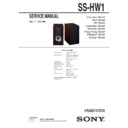
Sony SS-HW1 Service Manual ▷ View online
SERVICE MANUAL
Sony Corporation
Published by Sony Techno Create Corporation
SS-HW1
SPECIFICATIONS
SPEAKER SYSTEM
9-893-995-02
2014F33-1
©
2014.06
Canadian Model
AEP Model
UK Model
Australian Model
Mexican Model
Hong Kong Model
Malaysia Model
Korean Model
Ver. 1.1 2014.06
Speaker system
3 way, 4 drivers speaker
system
system
Loud speaker units
Woofer: 13 cm, cone type (1)
Tweeter: 2.5 cm, soft dome
type (1)
Super tweeter: 1.9 cm, soft
dome type (2)
Tweeter: 2.5 cm, soft dome
type (1)
Super tweeter: 1.9 cm, soft
dome type (2)
Enclosure type
Bass reflex
Rated impedance
4 ohms
Maximum input power
100 watts
Sensitivity level
83 dB (2.83 V, 1 m)
Effective Frequency
Range
Range
50 Hz - 50 kHz
Dimensions (w/h/d)
Approx. 171 mm × 309 mm ×
273 mm
273 mm
Mass
Approx. 5.1 kg
Supplied accessories
Speaker cords (2)
Speaker pads (8)
Operating Instructions (1)
Speaker pads (8)
Operating Instructions (1)
Design and specifications are subject to change
without notice.
without notice.
SS-HW1
2
SECTION 1
DISASSEMBLY
•
This set can be disassembled in the order shown below.
1-1. DISASSEMBLY FLOW
Note: Follow the disassembly procedure in the numerical order given.
1-2. GRILLE
ASSY
SET
1-9. TERMINAL
(TM1)
(Page
7)
1-3. SPEAKER (13 cm) (Woofer) (SP1)
(Page
(Page
3)
1-5. PANEL
BLOCK-2
(Page
5)
1-4. PANEL
BLOCK-1
(Page
4)
1-6. SPEAKER (18 mm) (Super Tweeter: Top) (SP2)
(Page
(Page
6)
1-8. SPEAKER (25 mm) (Tweeter) (SP4)
(Page
(Page
7)
1-2. GRILLE
ASSY
(Page
2)
1-7. SPEAKER (18 mm) (Super Tweeter: Front) (SP3)
(Page
(Page
6)
2 grille assy
1 catch
1 catch
1 catch
1 catch
SS-HW1
3
1-3. SPEAKER (13 cm) (Woofer) (SP1)
6 speaker (13 cm)
(woofer)
(SP1)
2 cover WF
1 four HEX. socket head
screws
(3.5)
3 Remove the speaker (13 cm) (SP1)
in the direction of the arrow.
– Front view –
speaker (13 cm)
(SP1)
(SP1)
terminals
position
position
Note: When installing the speaker (13 cm) (SP1),
make the position of terminals as shown in the
figure
below.
+ow to inVtDOO tKe VSeDNer FP 63
4 Push the protrusion,
and remove the claw.
4 Push the protrusion,
and remove the claw.
protrusion
protrusion
claw
claw
5 terminal (narrow)
[black]
5 terminal (wide)
[red]
SS-HW1
4
1-4. PANEL BLOCK-1
• Continued on 1-5 (page 5).
3 Holding the bottom of the panel block,
lift vertically in the direction the arrow
is
pointing.
1 six HEX. socket head
screws
(3.5)
1 three HEX. socket head
screws
(3.5)
4 two bosses
jig for speaker removal
panel block
2 Insert the jig into the space and slowly
remove the panel block.
Note
1: When using a jig, please work carefully
so as not to damage the panel block and
speaker
cabinet.
Note
2: If there are no jigs available, use something
like a metal ruler or the handle of a pair of
tweezers to remove the panel block.
JIG
When disassembling the unit, use the following
jig for speaker removal.
jig for speaker removal.
Part No.
Description
J-2501-238-A JIG FOR SPEAKER REMOVAL
panel block

