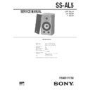
Sony SS-AL5 Service Manual ▷ View online
SS-AL5
AEP Model
UK Model
E Model
SPEAKER SYSTEM
SPECIFICATIONS
MICROFILM
SERVICE MANUAL
Speaker system
2-way, 2unit, bass reflex type
Speaker units
Woofer : 13 cm dia, cone type
Tweeter : 2.5 cm dia, dome type
Tweeter : 2.5 cm dia, dome type
Normal impedance
8
Ω
Rated input
40W
Maximum input level
120W
Sensitivity level
86dB/W/m
Effective frequency range
42 – 30,000Hz
Magnetically shielded
Dimensions
Dimensions
Approx. 230 x 350 x 335 mm (w/h/d)
including front grille
including front grille
Mass
9.5kg (net par speaker)
Design and specifications are subject to change without notice.
– 2 –
SECTION 1
EXPLODED VIEW
NOTE :
• -XX, -X mean standardized parts, so they
may have some difference from the original
one.
one.
• Items marked “ * ”are not stocked since they
are seldom required for routine service. Some
delay should be anticipated when ordering
these items.
delay should be anticipated when ordering
these items.
• The mechanical parts with no reference
number in the exploded views are not
supplied.
supplied.
7
8
4
4
3
2
10
1
11
5
6
9
SP1
SP2
1
4-986-694-01 FRAME, ORNAMENT
2
4-987-677-14 ECSAINE (TW)
3
X-4949-179-1 FRAME ASSY, GRILLE
* 4
4-963-075-01 CATCH
* 5
A-4384-353-A NETWORK BOARD ASSY
6
4-935-410-11 FASTENER
* 7
A-4384-353-A CABINET ASSY, SPEAKER
8
4-874-614-11 SCREW +BVTP 3.5X14 TYPE4
9
1-694-174-21 TERMINAL BOARD
10
7-682-568-04 SCREW +B 4X30
11
7-682-268-09 SCREW +K 4X30
SP1
1-505-478-11 SPEAKER (13cm) (WOOFER)
SP2
1-505-479-11 SPEAKER (2.5cm) (TWEETER)
Ref. No.
Part No.
Description
Remark
Ref. No.
Part No.
Description
Remark
– 3 –
SECTION 2
DIAGRAMS
2-1. SCHEMMATIC DIAGRAMS
L1
2.2mH
C4
2.2
WOOFER
WOOFER SECTION
R1
4.7
C2
2.2
C1
1.0
C3
3.3
R2
5.6
L2
0.27
R3
2.2
TWEETER
TWEETER SECTION
1
2
A
B
C
D
E
3
4
5
– 4 –
NOTE :
• Due to standardization, replacements in the
parts list may be different from the parts
specified in the diagrams or the components
used on the set.
specified in the diagrams or the components
used on the set.
• RESISTORS
All resistors are in ohms
METAL : Metal-film resistor
METAL OXIDE :Metal oxide-film resistor
F : nonflammable
METAL : Metal-film resistor
METAL OXIDE :Metal oxide-film resistor
F : nonflammable
• Items marked “ * ”are not stocked since they
are seldom required for routine service. Some
delay should be anticipated when ordering
these items.
delay should be anticipated when ordering
these items.
• CAPACITORS
uF :
µ
F
• COILS
uH :
µ
H
When indicating parts by reference num-
ber, please include the board.
ber, please include the board.
SECTION 3
ELECTRICAL PARTS LIST
Ref. No.
Part No.
Description
Remark
*
A-4384-353-A NETWORK BOARD, COMPLETE
*************************
< CAPACITOR >
C1
1-136-583-11 FILM
1.0uF
10%
200V
C2
1-136-585-11 FILM
2.2uF
10%
200V
C3
1-136-586-11 FILM
3.3uF
10%
200V
C4
1-136-585-11 FILM
2.2uF
10%
200V
< RESISTOR >
R1
1-217-668-11
4.7
10%
10W
R2
1-217-603-11
5.6
10%
10W
R3
1-217-804-11
2.2
10%
10W
< COIL >
L1
1-459-588-11 NETWORK, COILE
L2
1-459-819-11 NETWORK, COILE (M)
************************************************************
ACCESSORIES & PACKING MATERIALS
********************************
********************************
3-861-158-11 MANUAL INSTRUCTION (ERINGLISH,FRENCH,
DUTCH,SPANISH,ITALIAN,PORTUGUESE,
SWEDISH,GERMAN)
9-960-836-11
Sony Corporation
Home A&V Products Company
SS-AL5
NETWORK
97H021668-1D
Printed in Japan © 1997.8
Published by General Engineering Dept.
(Shibaura)
Display


