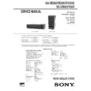
Sony SA-VE302 / SA-VE305 / SA-W305G / SS-CN305 / SS-V305 Service Manual ▷ View online
MICROFILM
SERVICE MANUAL
MICRO SATELLITE SYSTEM
US Model
Canadian Model
SA-VE305
AEP Model
UK Model
E Model
SA-VE302/VE305
SPECIFICATIONS
SA-VE302/VE305/W305G/
SS-CN305/V305
Photo: SS-CN305
Photo: SS-V305
• SA-VE302 and SA-VE305 consist of the following models respectively.
• SA-W305G is the same model as SA-W305, except only the color is different. This manual describes only the differences
from SA-W305. For further information, see the Service Manual of SA-W11/W303/W305 (9-922-813-
∏
).
SA-VE305
Super Woofer
SA-W305G
Center Speaker
SS-CN305
Front/Rear Speaker
SS-V305
SA-VE302
Super Woofer
SA-W305G
Front Speaker
SS-V305
– 2 –
Les composants identifiés par une
marque
marque
! sont critiquens pour la
sécurité.
Ne les remplacer que par une pièce
portant le numéro spécifié.
Ne les remplacer que par une pièce
portant le numéro spécifié.
The components identified by
mark
mark
! or dotted line with mark
! are critical for safety.
Replace only with part number
specified.
specified.
• Items marked “*” are not stocked since they
are seldom required for routine service. Some
delay should be anticipated when ordering
these items.
delay should be anticipated when ordering
these items.
• The mechanical parts with no reference num-
ber in the exploded views are not supplied.
NOTE:
• -XX and -X mean standardized parts, so they
may have some difference from the original
one.
one.
• Color Indication of Appearance Parts
Example:
KNOB, BALANCE (WHITE) . . . (RED)
KNOB, BALANCE (WHITE) . . . (RED)
↑
↑
Parts Color Cabinet's Color
Ref. No.
Part No.
Description
Remark
ACCESSORIES & PACKING MATERIALS
*******************************
*******************************
!
1-569-008-21 ADAPTOR, CONVERSION 2P
(VE302: SP/VE305: SP)
1-769-329-21 CORD, CONNECTION (PIN-PIN)
1-769-433-11 CORD, SPEAKER (10m) (VE305)
1-769-433-21 CORD, SPEAKER (2.5m)
1-769-433-11 CORD, SPEAKER (10m) (VE305)
1-769-433-21 CORD, SPEAKER (2.5m)
!
1-770-019-11 ADAPTOR, CONVERSION PLUG 3P
(VE302: UK/VE305: UK)
3-866-761-11 MANUAL, INSTRUCTION (ENGLISH, FRENCH)
3-866-761-21 MANUAL, INSTRUCTION (GERMAN, SPANISH,
3-866-761-21 MANUAL, INSTRUCTION (GERMAN, SPANISH,
DUTCH, SWEDISH, ITALIAN, PORTUGUESE,
POLISH, RUSSIAN, DANISH, FINNISH,
CHINESE) (VE302: G, SP/VE305: G, SP)
4-972-322-01 FOOT (Y) (for SS-CN305)
• EXPLODED VIEWS AND PATRS LIST
• Abbreviation
CND : Canadian model
G
G
: German model
SP
: Singapore model
(1)
SA-VE302/VE305
– 3 –
Ref. No.
Part No.
Description
Remark
Ref. No.
Part No.
Description
Remark
(2)
SA-W305G
(Refer to service Manual page 9, 12)
(Refer to service Manual page 9, 12)
1
X-4951-284-1 FRAME ASSY, GRILLE
2
X-4951-285-1 PANEL ASSY, FRONT
3
1-669-259-11 CONTROL BOARD
4
4-973-938-41 KNOB (A), PUSH
5
4-999-482-21 KNOB (VOL)
6
A-4411-511-A CABINET ASSY, SPEAKER
* 7
4-999-088-11 PANEL, REAR (US)
* 7
4-999-088-23 PANEL, REAR (SP)
* 7
4-999-088-31 PANEL, REAR (G)
8
3-710-901-11 SCREW, TAPPING
! 9
1-782-603-11 CORD, POWER (G, SP)
! 9
1-782-604-11 CORD, POWER (US)
* 10
3-703-244-00 BUSHING (2104), CORD
11
A-4407-548-A MAIN BOARD, COMPLETE (US)
11
A-4407-550-A MAIN BOARD, COMPLETE (G)
11
A-4407-551-A MAIN BOARD, COMPLETE (SP)
12
1-670-254-11 POWER IC BOARD
13
4-999-093-01 PACKING
14
4-981-864-01 FOOT
SP301
1-505-925-11 SPEAKER (16cm)
! T1
1-431-774-11 TRANSFORMER, POWER (US)
! T1
1-431-775-11 TRANSFORMER, POWER (G)
! T1
1-431-776-11 TRANSFORMER, POWER (SP)
************************************************************
**************
HARDWARE LIST
**************
HARDWARE LIST
**************
#1
7-685-665-79 SCREW +BVTP 4X25 TYPE2 N-S
#2
7-685-647-79 SCREW +P 3X10 TYPE2 NON-SLIT
#3
7-685-664-79 SCREW +PTP 4X20 TYPE1
#4
7-685-663-79 SCREW +BVTP 4X16 TYPE2 N-S
#5
7-685-648-79 SCREW +P 3X12 TYPE2 NON-SLIT
#6
7-685-660-19 SCREW +BVTP 4X10 TYPE2 N-S
#7
7-685-165-01 SCREW +PTP 4X25 TYPE1
The components identified by
mark
mark
! or dotted line with
mark
! are critical for safety.
Replace only with part num-
ber specified.
ber specified.
Les composants identifiés par une
marque
marque
! sont critiques pour la
sécurité.
Ne les remplacer que par une pièce
portant le numéro spécifié.
Ne les remplacer que par une pièce
portant le numéro spécifié.
14
9
9
10
7
11
13
12
3
4
1
2
5
6
A
A
4
SP301
not supplied
supplied with
RV201, 202
RV201, 202
#2
not
supplied
supplied
not
supplied
supplied
#1
#2
#5
#5
#5
not
supplied
supplied
not
supplied
supplied
T1
not
supplied
supplied
not
supplied
supplied
#3
#3
#2
#4
#2
#7
#2
#6
#4
8
G, SP
US
– 4 –
(3)
SS-CN305
Ref. No.
Part No.
Description
Remark
Ref. No.
Part No.
Description
Remark
101
X-4951-173-1 FRAME ASSY, GRILLE
102
7-685-659-79 SCREW +BVTP 4X8 TYPE2 IT-3
103
7-685-661-79 SCREW +BVTP 4X12 TYPE2 SLIT
104
X-4951-174-1 CABINET ASSY, SPEAKER
105
4-929-125-01 SCREW (M4X16), TAPPING
106
1-537-775-11 TERMINAL BOARD
107
X-4951-182-1 PANEL ASSY, FRONT
SP501
1-529-294-11 SPEAKER
51
X-4951-167-1 FRAME ASSY, GRILLE
52
7-685-659-79 SCREW +BVTP 4X8 TYPE2 IT-3
53
X-4951-168-1 CABINET ASSY, SPEAKER
54
7-685-661-79 SCREW +BVTP 4X12 TYPE2 SLIT
55
1-537-775-11 TERMINAL BOARD
56
4-929-125-01 SCREW (M4X16), TAPPING
57
X-4951-183-1 PANEL ASSY, FRONT
SP401
1-529-294-11 SPEAKER
SP402
1-529-294-11 SPEAKER
not supplied
not supplied
not
supplied
supplied
SP402
SP401
56
54
55
52
52
57
51
53
(4)
SS-V305
105
106
104
103
107
101
102
not
supplied
supplied
not supplied
SP501
not supplied
SA-VE302/VE305/W305G/SS-CN305/V305
Sony Corporation
Home A&V Products Company
9-928-868-11
99D0587-1
Printed in Japan © 1999. 4
Published by Quality Assurance Dept.
(Shinagawa)
Display


