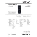
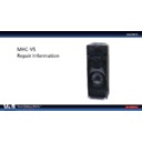
Sony MHC-V5 Service Manual ▷ View online
MHC-V5
REVISION HISTORY
Ver.
Date
Description of Revision
1.0
2014.02
New
1.1
2014.04
Addition of Mexican model
Change of Part for Ref. No. C088 on the ARAGON board
Change of Ref. No. for connector on the ARAGON board (CN306→CN302)
Deletion of Part for Ref. No. C668, CN101, CN106, CN301, CN305, D104 to D115, D118, D119, IC608,
R169, R205, R239, R247, R261, R272, R703, R706, R713 and R714 on the ARAGON board
Addition of Part for Ref. No. R726 on the ARAGON board
Deletion of Part for Ref. No. C1002, C1009, L1001, Q1072, R1031 and R1590 on the D-AMP board
Deletion of Part for Ref. No. D2110, D2111, R2131 and R2132 on the TOP KEY A board
Deletion of Part for Ref. No. D2150, D2152, R2150 and R2160 on the TOP KEY B board
Addition of Part for Ref. No. R2210 to R2215 on the USB board (Except US model)
Deletion of Part for Ref. No. C2201, C2205, D2202, D2203, D2205, D2207, D2208 to D2213, ET001 and
ET002 on the USB board (Except US model)
Change of Part for FLEXIBLE FLAT CABLE
Change of Part No. for SIDE PANEL and Deletion of SCREW CAP (4 pieces)
Deletion of Ref. No. FC4, 6, 7, 8 (Except US model)
Change of Part No. for NFC MODULE, VOLUME KNOB, FRONT PANEL ASSY and
TOP ASSY PANEL
Deletion of DUCT, SCREW (BV/RING) (6 pieces), CUSHION (E), CUSHION (E15),
CUSHION (E 0.5) (4 pieces), SHEET (FL), CUSHION (H) (4 pieces), CUSHION (E 1) (4 pieces)
and SCREW (+BVTP 3X8) (4 pieces)
Change to wire with terminal by Deletion of GROUND (USB L) PLATE and GROUND (USB R)
PLATE (Except US model)
Change of Part No. for POWER-SUPPLY CORD SET (120V AC area in E, Chilean and Peruvian models)
Change of D-AMP and SPEAKER LED boards (Suffi x-12) (SUPPLEMENT-1)
(SMR-13066)
1.2
2014.07
Addition of Argentina model
1.3
2014.08
Addition of Australian model
Addition of FL, TOP KEY A, TOP KEY B and USB boards for Australian model (Suffi x-21)
(SUPPLEMENT-2)
How to search for a contact point of signal lines or the like in DIAGRAMS SECTION
If a contact point of a BLOCK DIAGRAM, PRINTED WIRING BOARD or SCHEMATIC DIAGRAM is shown in a different page, use
the PDF fi le search function to fi nd one.
If a contact point of a BLOCK DIAGRAM, PRINTED WIRING BOARD or SCHEMATIC DIAGRAM is shown in a different page, use
the PDF fi le search function to fi nd one.
e.g.) If a contact point is shown as
, follow the procedure below.
Procedure:
1. Press the [F] key while pressing the [Ctrl] key.
2. Input “>001Z” in the search box and press the [Enter] key.
3. The relevant part (page), where the contact point is shown, appears.
1. Press the [F] key while pressing the [Ctrl] key.
2. Input “>001Z” in the search box and press the [Enter] key.
3. The relevant part (page), where the contact point is shown, appears.
Note: If you still see the original page, press the [Enter] key again.

