Sony MHC-GT22 / MHC-GT22BP / MHC-GT44 / MHC-GT44BP / MHC-GT55 / MHC-GT55BP / SS-GT44 / SS-GT55M / SS-WG44 / SS-WG55 Service Manual ▷ View online
SERVICE MANUAL
SPEAKER SYSTEM
SPECIFICATIONS
SS-GT44/GT55M/WG44/
WG55
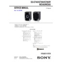
Photo: SS-GT44
Ver. 1.1 2007.12
• SS-GT44 is the front speaker in MHC-GT22/GT22BP/GT44/GT44BP.
• SS-GT55M is the front speaker in MHC-GT55/GT55BP.
• SS-WG44 is the subwoofer in MHC-GT44/GT44BP.
• SS-WG55 is the subwoofer in MHC-GT55/GT55BP.
• SS-GT55M is the front speaker in MHC-GT55/GT55BP.
• SS-WG44 is the subwoofer in MHC-GT44/GT44BP.
• SS-WG55 is the subwoofer in MHC-GT55/GT55BP.
9-887-728-02
2007L05-1
© 2007.12
© 2007.12
Sony Corporation
Audio Business Group
Published by Sony Techno Create Corporation
Published by Sony Techno Create Corporation
E Model
SS-GT44/GT55M/WG44/WG55
Australian Model
SS-GT44/WG44
Photo: SS-GT55M
Photo: SS-WG44
Photo: SS-WG55
Front speaker SS-GT55M for MHC-GT55/
GT55BP
GT55BP
Speaker system: 3-way, 3-unit, bass-reflex
type
Speaker units: Subwoofer 15 cm,
cone type, Woofer 15 cm, cone type,
Tweeter 4 cm, horn type
Rated impedance: 6
type
Speaker units: Subwoofer 15 cm,
cone type, Woofer 15 cm, cone type,
Tweeter 4 cm, horn type
Rated impedance: 6
Ω
Dimensions (w/h/d): Approx. 250
×
405
×
300 mm
Mass: Approx. 5.3 kg net per speaker
Subwoofer SS-WG55 for MHC-GT55/GT55BP
Speaker system: 1-unit, bass-reflex type
Speaker units: Woofer 25 cm, cone type
Rated impedance: 6
Speaker units: Woofer 25 cm, cone type
Rated impedance: 6
Ω
Dimensions (w/h/d): Approx. 320
×
405
×
360 mm
Mass: Approx. 8.4 kg
Mass: Approx. 8.4 kg
Front speaker SS-GT44 for MHC-GT44/
GT44BP/GT22/GT22BP
GT44BP/GT22/GT22BP
Speaker system: 3-way, 3-unit, bass-reflex
type
type
Speaker units: Subwoofer 13 cm,
cone type, Woofer 13 cm, cone type,
Tweeter 4 cm, horn type
Rated impedance: 6
cone type, Woofer 13 cm, cone type,
Tweeter 4 cm, horn type
Rated impedance: 6
Ω
Dimensions (w/h/d): Approx. 240
×
365
×
250 mm
Mass: Approx. 4.0 kg net per speaker
Subwoofer SS-WG44 for MHC-GT44/GT44BP
Speaker system: 1-unit, bass-reflex
type
Speaker units: Woofer 20 cm, cone
type
Rated impedance: 6
type
Speaker units: Woofer 20 cm, cone
type
Rated impedance: 6
Ω
Dimensions (w/h/d): Approx. 270
×
325
×
345 mm
Mass: Approx. 5.8 kg
Design and specifications are subject to
change without notice.
change without notice.
•
JIG
When disassembling the set, use the following jig (for
speaker removal).
Part No.: J-2501-238-A JIG FOR SPEAKER REMOVAL
When disassembling the set, use the following jig (for
speaker removal).
Part No.: J-2501-238-A JIG FOR SPEAKER REMOVAL
SS-GT44/GT55M/WG44/WG55
2
Note:
Follow the disassembly procedure in the numerical order given.
1-1. FRONT PANEL ASSY (SS-GT44/GT55M)
SECTION 1
DISASSEMBLY
3
Raise the front panel assy a little by little
from bottom to top of the set.
from bottom to top of the set.
9
front panel assy
5
two screws (3.5)
7
loudspeaker (4 cm) (SP2)
6
tweeter spacer
4
1
Insert a flat-tip screwdriver into a recess
in the bottom of the set
to raise the front panel assy a little.
in the bottom of the set
to raise the front panel assy a little.
2
Insert the jig (J-2501-238-A) into a space
made by inserting the screwdriver,
and raise the front panel assy gradually.
made by inserting the screwdriver,
and raise the front panel assy gradually.
2
Insert the jig (J-2501-238-A) into a space
made by inserting the screwdriver,
and raise the front panel assy gradually.
made by inserting the screwdriver,
and raise the front panel assy gradually.
SS-GT44/GT55M/WG44/WG55
3
1-2. FRONT PANEL ASSY (SS-WG44/WG55)
4
front panel assy
1
Insert a flat-tip screwdriver into a recess
in the bottom of the set
to raise the front panel assy a little.
in the bottom of the set
to raise the front panel assy a little.
2
Insert the jig (J-2501-238-A) into a space
made by inserting the screwdriver,
and raise the front panel assy gradually.
made by inserting the screwdriver,
and raise the front panel assy gradually.
2
Insert the jig (J-2501-238-A) into a space
made by inserting the screwdriver,
and raise the front panel assy gradually.
made by inserting the screwdriver,
and raise the front panel assy gradually.
3
Raise the front panel assy a little by little
from bottom to top of the set.
from bottom to top of the set.
4
SS-GT44/GT55M/WG44/WG55
SECTION 2
EXPLODED VIEWS
2-1.
SS-GT44/GT55M
•
Items marked “*” are not stocked since they
are seldom required for routine service. Some
delay should be anticipated when ordering
these items.
are seldom required for routine service. Some
delay should be anticipated when ordering
these items.
•
The mechanical parts with no reference
number in the exploded views are not supplied.
number in the exploded views are not supplied.
NOTE:
•
-XX and -X mean standardized parts, so they
may have some difference from the original
one.
may have some difference from the original
one.
•
Color Indication of Appearance Parts
Example:
KNOB, BALANCE (WHITE) . . . (RED)
Example:
KNOB, BALANCE (WHITE) . . . (RED)
↑
↑
Parts Color
Cabinet's Color
1
not supplied
not supplied
not supplied
not supplied
not supplied
not
supplied
supplied
not supplied
not supplied
not supplied
SP1
SP2
SP3
2
2
2
2
3
Ref. No.
Part No.
Description
Remark
1
A-1234-338-A OVERALL ASSY (GT44)
1
A-1234-348-A OVERALL ASSY (GT55M)
2
4-874-614-82 SCREW
3
4-986-971-12 SCREW (3.5)
SP1
1-826-622-11 LOUDSPEAKER (13 cm) (GT44)
SP1
1-826-625-11 LOUDSPEAKER (15 cm) (GT55M)
SP2
1-826-624-12 LOUDSPEAKER (4 cm)
SP3
1-826-623-11 LOUDSPEAKER (13 cm) (GT44)
SP3
1-826-626-11 LOUDSPEAKER (15 cm) (GT55M)
Ref. No.
Part No.
Description
Remark
Display

