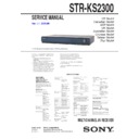
Sony HT-SF2300 / HT-SS2300 / STR-KS2300 Service Manual ▷ View online
SERVICE MANUAL
Published by Sony Techno Create Corporation
Sony Corporation
Audio&Video Business Group
STR-KS2300
SPECIFICATIONS
MULTI CHANNEL AV RECEIVER
9-889-108-02
2008I05-1
©
2008.09
US Model
Canadian Model
AEP Model
UK Model
Australian Model
Chinese Model
Taiwan Model
Thai Model
Ver. 1.1 2008.09
• STR-KS2300 is the receiver section in HT-SF2300/SS2300.
This receiver incorporates Dolby* Digital and Pro
Logic Surround and the DTS** Digital Surround
System.
Logic Surround and the DTS** Digital Surround
System.
* Manufactured under license from Dolby
Laboratories.
Dolby, Pro Logic and the double-D symbol are
trademarks of Dolby Laboratories.
** Manufactured under license under U.S. Patent
#’s: 5,451,942; 5,956,674; 5,974,380; 5,978,762;
6,487,535 & other U.S. and worldwide patents
issued & pending. DTS and DTS Digital
Surround are registered trademarks and the DTS
logos and Symbol are trademarks of DTS, Inc.
© 1996-2007 DTS, Inc. All Rights Reserved.
This receiver incorporates High-Definition
Multimedia Interface (HDMI™) technology.
HDMI, the HDMI logo and High-Definition
Multimedia Interface are trademarks or registered
trademarks of HDMI Licensing LLC.
Multimedia Interface (HDMI™) technology.
HDMI, the HDMI logo and High-Definition
Multimedia Interface are trademarks or registered
trademarks of HDMI Licensing LLC.
“x.v.Colour” and “x.v.Colour” logo are trademarks
of Sony Corporation.
of Sony Corporation.
“BRAVIA” and are trademarks of Sony
Corporation.
Corporation.
Design and specifications are subject to
change without notice.
change without notice.
About area codes
The area code of the receiver you purchased is
shown on the lower portion of the rear panel
(see the illustration below).
shown on the lower portion of the rear panel
(see the illustration below).
Any differences in operation, according to the area
code, are clearly indicated in the text, for example,
“Models of area code AA only”.
code, are clearly indicated in the text, for example,
“Models of area code AA only”.
FRONT R
FRONT L
SUR R
SUR L
CENTER SUBWOOFER
Area code
AUDIO POWER
SPECIFICATIONS
POWER OUTPUT AND TOTAL
HARMONIC DISTORTION:
(Models of area code U, UC only)
With 3 ohm loads, both channels driven, from
170 – 20,000 Hz; rated 84 watts per channel
minimum RMS power, with no more than 1%
total harmonic distortion from 250 milliwatts
to rated output.
With 3 ohm loads, both channels driven, from
170 – 20,000 Hz; rated 84 watts per channel
minimum RMS power, with no more than 1%
total harmonic distortion from 250 milliwatts
to rated output.
Amplifier section
Models of area code U, UC, CA
Power Output
1)
Stereo mode (rated) 84 W + 84 W
(3 ohms at 170 –
20,000 Hz, THD 1%)
20,000 Hz, THD 1%)
Surround mode (reference)
RMS Output
(3 ohms at 1 kHz,
THD 10%)
FRONT
(3 ohms at 1 kHz,
THD 10%)
FRONT
2)
: 143 W/ch
CENTER
2)
: 143 W
SUR
2)
: 143 W/ch
(1.5 ohms at 80 Hz,
THD 10%)
THD 10%)
SUBWOOFER
2)
: 285 W
Models of area code CEL, CEK, AU, TW
Power Output
1)
Stereo mode (rated) 108 W + 108 W
(3 ohms at 1 kHz,
THD 1%)
THD 1%)
Surround mode (reference)
RMS Output
(3 ohms at 1 kHz,
THD 10%)
FRONT
(3 ohms at 1 kHz,
THD 10%)
FRONT
2)
: 143 W/ch
CENTER
2)
: 143 W
SUR
2)
: 143 W/ch
(1.5 ohms at 80 Hz,
THD 10%)
THD 10%)
SUBWOOFER
2)
: 285 W
Models of area code TH
Power Output
1)
Stereo mode (rated) 90 W + 90 W
(3 ohms at 1 kHz,
THD 1%)
THD 1%)
Models of area code CN
RMS Output
(3 ohms at 1 kHz, THD
10%)
FRONT
10%)
FRONT
2)
: 125 W/ch
CENTER
2)
: 125 W
SUR
2)
: 125 W/ch
(1.5 ohms at 80 Hz, THD
10%)
SUBWOOFER
10%)
SUBWOOFER
2)
: 210 W
FRONT: 100 W
CENTER: 100 W
SUR: 100 W
SUBWOOFER: 100 W
CENTER: 100 W
SUR: 100 W
SUBWOOFER: 100 W
1)
Measured under the following conditions:
2)
Reference power output for front, center, surround
speakers and subwoofer. Depending on the sound
field settings and the source, there may be no
sound output.
speakers and subwoofer. Depending on the sound
field settings and the source, there may be no
sound output.
Inputs
Analog
Sensitivity: 1 V/50 kohms
Digital (Coaxial) Impedance: 75 ohms
Tone
Gain levels
±10 dB, 0.5 dB step
Reproduction frequency range:
28 – 20,000 Hz
Area code
Power requirements
U, UC, CA
120 V AC, 60 Hz
CEL, CEK
230 V AC, 50 Hz
AU
240 V AC, 50 Hz
TW
110 V AC, 60 Hz
TH, CN
220 V AC, 50 Hz
FM tuner section
Tuning range
87.5 - 108.0 MHz
Antenna
FM wire antenna
Antenna terminals
75 ohms, unbalanced
Intermediate frequency
10.7 MHz
AM tuner section
Tuning range
General
Power requirements
Power output (DIGITAL MEDIA PORT)
DC OUT:
5 V, 700 mA MAX
Power consumption
Power consumption (during standby mode)
0.3 W (When “CONTROL
FOR HDMI” in VIDEO
menu is set to “CTRL
OFF”)
FOR HDMI” in VIDEO
menu is set to “CTRL
OFF”)
Dimensions (w/h/d) (Approx.)
430 × 66.7 × 333 mm
(17 × 2 3/4 × 13 1/8 inches)
including projecting parts
and controls
(17 × 2 3/4 × 13 1/8 inches)
including projecting parts
and controls
Mass (Approx.)
3.5 kg (7 lb 12 oz)
Area code
Tuning scale
10 kHz step
9 kHz step
U, UC, CA, AU
530 –
1,710 kHz
1,710 kHz
3)
531 –
1,710 kHz
1,710 kHz
3)
TW, TH, CN
530 –
1,610 kHz
1,610 kHz
3)
531 –
1,602 kHz
1,602 kHz
3)
CEL, CEK
–
531 –
1,602 kHz
1,602 kHz
Area code
Power requirements
U, UC, CA
120 V AC, 60 Hz
CEL, CEK
230 V AC, 50/60 Hz
AU
240 V AC, 50 Hz
TW
110 V AC, 60 Hz
CN
220 V AC, 50/60 Hz
Area code
Power consumption
U, CEL, CEK, AU,
TW, CN
TW, CN
165 W
UC, CA
165 W (for USA)
245 VA (for CANADA)
245 VA (for CANADA)
TH
140 W
Antenna
Loop antenna
Intermediate frequency
450 kHz
3)
You can change the AM tuning scale to 9 kHz or
10 kHz. After tuning in any AM station, turn off
the receiver. While holding down PRESET
TUNING +, press
10 kHz. After tuning in any AM station, turn off
the receiver. While holding down PRESET
TUNING +, press
. All preset stations will be
erased when you change the tuning scale. To reset
the scale to 10 kHz (or 9 kHz), repeat the
procedure.
the scale to 10 kHz (or 9 kHz), repeat the
procedure.
Power Output
1) 2)
TH
220
− 230 V AC, 50/60 Hz
STR-KS2300
2
1.
SERVICING NOTES
............................................. 3
2. GENERAL
.................................................................. 4
3. DISASSEMBLY
3-1. Disassembly Flow .......................................................... 6
3-2. Case
3-2. Case
................................................................................ 6
3-3. HDMI
Board
................................................................... 7
3-4. Front Panel Block .......................................................... 7
3-5. MAIN
3-5. MAIN
Board
................................................................... 8
4.
TEST MODE
............................................................
9
5.
ELECTRICAL CHECK
.........................................
9
6. DIAGRAMS
6-1. Block Diagram - MAIN Section - .................................. 10
6-2. Block Diagram - HDMI Section - .................................. 11
6-3. Block Diagram - DSP Section - ..................................... 12
6-4. Block Diagram - AMP Section - .................................... 13
6-5. Block Diagram - POWER SUPPLY Section - ............... 14
6-6. Printed
Wiring
Board
- MAIN Board (Component Side) - ............................... 16
6-7. Printed
Wiring
Board
- MAIN Board (Conductor Side) - ................................. 17
6-8. Schematic Diagram - MAIN Board (1/5) - .................... 18
6-9. Schematic Diagram - MAIN Board (2/5) - .................... 19
6-10. Schematic Diagram - MAIN Board (3/5) - .................... 20
6-11. Schematic Diagram - MAIN Board (4/5) - .................... 21
6-12. Schematic Diagram - MAIN Board (5/5) - .................... 22
6-13. Printed Wiring Board - IO Board - ................................ 23
6-14. Schematic Diagram - IO Board - .................................... 23
6-15. Printed Wiring Board - HDMI Board (Side A) - ............ 24
6-16. Printed Wiring Board - HDMI Board (Side B) - ........... 25
6-17. Schematic Diagram - HDMI Board (1/2) - .................... 26
6-18. Schematic Diagram - HDMI Board (2/2) - .................... 27
6-19. Printed Wiring Board - DCAC Board - ......................... 28
6-20. Schematic Diagram - DCAC Board - ............................ 28
6-21. Printed Wiring Boards - PANEL Section - ..................... 29
6-22. Schematic Diagram - IR Board - ................................... 30
6-23. Schematic Diagram - DISPLAY Board - ........................ 31
6-24. Printed Wiring Board - SMPS Board - .......................... 32
6-25. Schematic Diagram - SMPS Board - ............................. 33
7.
EXPLODED VIEWS
7-1. Case, HDMI Board Section ........................................... 52
7-2. Front Panel Section ........................................................ 53
7-3. MAIN Board Section ..................................................... 54
7-2. Front Panel Section ........................................................ 53
7-3. MAIN Board Section ..................................................... 54
8.
ELECTRICAL PARTS LIST
.............................. 55
TABLE OF CONTENTS
SAFETY-RELATED COMPONET WARNING!
COMPONENTS IDENTIFIED BY MARK 0 OR DOTTED LINE
WITH MARK 0 ON THE SCHEMATIC DIAGRAMS AND IN
THE PARTS LIST ARE CRITICAL TO SAFE OPERATION.
REPLACE THESE COMPONENTS WITH SONY PARTS
WITH MARK 0 ON THE SCHEMATIC DIAGRAMS AND IN
THE PARTS LIST ARE CRITICAL TO SAFE OPERATION.
REPLACE THESE COMPONENTS WITH SONY PARTS
WHOSE PART NUMBERS APPEAR AS SHOWN IN THIS
MANUAL OR IN SUPPLEMENTS PUBLISHED BY SONY.
MANUAL OR IN SUPPLEMENTS PUBLISHED BY SONY.
ATTENTION AU COMPOSANT AYANT RAPPORT
À LA SÉCURITÉ!
LES COMPOSANTS IDENTIFIÉS PAR UNE MARQUE 0 SUR
LES DIAGRAMMES SCHÉMATIQUES ET LA LISTE DES
PIÈCES SONT CRITIQUES POUR LA SÉCURITÉ DE FONC-
TIONNEMENT. NE REMPLACER CES COM- POSANTS QUE
PAR DES PIÈCES SONY DONT LES NUMÉROS SONT DON-
NÉS DANS CE MANUEL OU DANS LES SUPPLÉMENTS
PUBLIÉS PAR SONY.
LES DIAGRAMMES SCHÉMATIQUES ET LA LISTE DES
PIÈCES SONT CRITIQUES POUR LA SÉCURITÉ DE FONC-
TIONNEMENT. NE REMPLACER CES COM- POSANTS QUE
PAR DES PIÈCES SONY DONT LES NUMÉROS SONT DON-
NÉS DANS CE MANUEL OU DANS LES SUPPLÉMENTS
PUBLIÉS PAR SONY.
SAFETY CHECK-OUT
After correcting the original service problem, perform the follow-
ing safety check before releasing the set to the customer:
Check the antenna terminals, metal trim, “metallized” knobs,
screws, and all other exposed metal parts for AC leakage.
Check leakage as described below.
After correcting the original service problem, perform the follow-
ing safety check before releasing the set to the customer:
Check the antenna terminals, metal trim, “metallized” knobs,
screws, and all other exposed metal parts for AC leakage.
Check leakage as described below.
LEAKAGE TEST
The AC leakage from any exposed metal part to earth ground and
from all exposed metal parts to any exposed metal part having a
return to chassis, must not exceed 0.5 mA (500 microamperes.).
Leakage current can be measured by any one of three methods.
1. A commercial leakage tester, such as the Simpson 229 or RCA
WT-540A. Follow the manufacturers’ instructions to use these
instruments.
instruments.
2. A battery-operated AC milliammeter. The Data Precision 245
digital multimeter is suitable for this job.
3. Measuring the voltage drop across a resistor by means of a
VOM or battery-operated AC voltmeter. The “limit” indication
is 0.75 V, so analog meters must have an accurate low-voltage
scale. The Simpson 250 and Sanwa SH-63Trd are examples
of a passive VOM that is suitable. Nearly all battery operated
digital multimeters that have a 2 V AC range are suitable. (See
Fig. A)
is 0.75 V, so analog meters must have an accurate low-voltage
scale. The Simpson 250 and Sanwa SH-63Trd are examples
of a passive VOM that is suitable. Nearly all battery operated
digital multimeters that have a 2 V AC range are suitable. (See
Fig. A)
Fig. A. Using an AC voltmeter to check AC leakage.
1.5 kΩ
0.15 µF
AC
voltmeter
(0.75 V)
To Exposed Metal
Parts on Set
Earth Ground
Notes on chip component replacement
•
•
Never reuse a disconnected chip component.
•
Notice that the minus side of a tantalum capacitor may be dam-
aged by heat.
aged by heat.
Ver. 1.1
STR-KS2300
3
SECTION 1
SERVICING NOTES
UNLEADED SOLDER
Boards requiring use of unleaded solder are printed with the lead-
free mark (LF) indicating the solder contains no lead.
(Caution: Some printed circuit boards may not come printed with
Boards requiring use of unleaded solder are printed with the lead-
free mark (LF) indicating the solder contains no lead.
(Caution: Some printed circuit boards may not come printed with
the lead free mark due to their particular size)
: LEAD FREE MARK
Unleaded solder has the following characteristics.
• Unleaded solder melts at a temperature about 40 °C higher
• Unleaded solder melts at a temperature about 40 °C higher
than ordinary solder.
Ordinary soldering irons can be used but the iron tip has to be
applied to the solder joint for a slightly longer time.
applied to the solder joint for a slightly longer time.
Soldering irons using a temperature regulator should be set to
about 350 °C.
about 350 °C.
Caution: The printed pattern (copper foil) may peel away if the
heated tip is applied for too long, so be careful!
heated tip is applied for too long, so be careful!
• Strong viscosity
Unleaded solder is more viscou-s (sticky, less prone to fl ow)
than ordinary solder so use caution not to let solder bridges
occur such as on IC pins, etc.
than ordinary solder so use caution not to let solder bridges
occur such as on IC pins, etc.
• Usable with ordinary solder
It is best to use only unleaded solder but unleaded solder may
also be added to ordinary solder.
also be added to ordinary solder.
NOTE OF REPLACING THE IC1131 ON THE MAIN
BOARD
IC1131 on the MAIN board cannot exchange with single. When
IC1131 on the MAIN board is damaged, exchange the entire
mounted board.
BOARD
IC1131 on the MAIN board cannot exchange with single. When
IC1131 on the MAIN board is damaged, exchange the entire
mounted board.
NOTE OF REPLACING THE IC3511 AND IC3513 ON
THE HDMI BOARD
IC3511 and IC3513 on the HDMI board cannot exchange with sin-
gle. When IC3511 and IC3513 on the HDMI board are damaged,
exchange the entire mounted board.
THE HDMI BOARD
IC3511 and IC3513 on the HDMI board cannot exchange with sin-
gle. When IC3511 and IC3513 on the HDMI board are damaged,
exchange the entire mounted board.
STR-KS2300
4
SECTION 2
GENERAL
Description and location of parts
Front panel
Getting Started
Receiver
MASTER VOLUME
AUTO CAL MIC
MUTING
INPUT SELECTOR
PRESET
ACTIVE
STANDBY
TUNING
SOUND FIELD
Name
Function
" /
(on/standby)
Press to turn the receiver
on or off.
on or off.
# ACTIVE
STANDBY
lamp
lamp
Lights up in amber when
the CONTROL FOR
HDMI is set to on and the
receiver is on standby
mode.
the CONTROL FOR
HDMI is set to on and the
receiver is on standby
mode.
$ Display
The current status of the
selected component or a
list of selectable items
appears here.
selected component or a
list of selectable items
appears here.
% PRESET TUNING
+/–
Press to select a preset
station.
station.
& SOUND FIELD
+/–
Press to select a sound
field.
field.
' INPUT
SELECTOR +/–
Press to select the input
source to playback.
source to playback.
( AUTO CAL MIC
jack
Connects to the supplied
optimizer microphone for
the Auto Calibration
function.
optimizer microphone for
the Auto Calibration
function.
Name
Function
) MASTER
VOLUME
Turn to adjust the volume
level of all speakers at the
same time.
level of all speakers at the
same time.
* MUTING
Press to turn off the sound
temporarily.
Press MUTING again to
restore the sound.
temporarily.
Press MUTING again to
restore the sound.
+ Remote sensor
Receives signals from
remote commander.
remote commander.
About the indicators on the display
L
C
R
SL
SR
SW
D.RANGE
RDS
ST MONO
MEMORY
S
DIGITAL
DTS
HDMI
PL
OPT COAX
R
RB
RT
RE
RG
SLEEP
LFE
Name
Function
" LFE
Lights up when the disc being
played back contains an LFE
(Low Frequency Effect) channel
and the LFE channel signal is
actually being reproduced.
played back contains an LFE
(Low Frequency Effect) channel
and the LFE channel signal is
actually being reproduced.
# SLEEP
Lights up when the sleep timer is
activated.
activated.
$ Playback
channel
indicators
indicators
L
R
C
SL
SR
S
The letters (L, C, R, etc.) indicate
the channels being played back.
The boxes around the letters vary
to show how the receiver
downmixes the source sound.
Front Left
Front Right
Center (monaural)
Surround Left
Surround Right
Surround (monaural or the
surround components obtained
by Pro Logic processing)
Example:
Recording format (Front/
Surround): 3/2.1
Sound Field: A.F.D. AUTO
%
DIGITAL Lights up when receiver is
decoding Dolby Digital signals.
Note
When playing a Dolby Digital
format disc, be sure that you
have made digital connections
and that IN MODE is set to
“AUTO”.
Note
When playing a Dolby Digital
format disc, be sure that you
have made digital connections
and that IN MODE is set to
“AUTO”.
& HDMI
Lights up when a playback
component is connected to this
receiver using an HDMI jack.
component is connected to this
receiver using an HDMI jack.
L
C
R
SL
SR
SW
' Preset
station
indicators
indicators
Lights up when using the receiver
to tune in radio stations you have
preset. For details on presetting
radio stations.
to tune in radio stations you have
preset. For details on presetting
radio stations.
( D.RANGE
Lights up when dynamic range
compression is activated.
compression is activated.
) Tuner
indicators
Lights up when using the
receiver to tune in radio stations,
etc.
Note
“RDS” lights up for models of
area code CEL, CEK only.
receiver to tune in radio stations,
etc.
Note
“RDS” lights up for models of
area code CEL, CEK only.
* MEMORY
Lights up when a memory
function, such as Preset Memory,
etc., is activated.
function, such as Preset Memory,
etc., is activated.
+ COAX
Lights up when DVD input is
selected and the source signal is
a digital signal being input
through the COAX IN jack.
selected and the source signal is
a digital signal being input
through the COAX IN jack.
, OPT
Lights up when IN MODE is set
to “AUTO” and the source signal
is a digital signal being input
through the OPT IN jack.
to “AUTO” and the source signal
is a digital signal being input
through the OPT IN jack.
- PL/
PLII
“PL” lights up when the
receiver applies Pro Logic
processing to 2 channel signals
in order to output the center and
surround channel signals.
“PLII” lights up when the
processing to 2 channel signals
in order to output the center and
surround channel signals.
“PLII” lights up when the
Pro Logic II Movie/Music
decoder is activated.
decoder is activated.
. DTS
Lights up when the receiver is
decoding DTS signals.
Note
When playing a DTS format
disc, be sure that you have made
digital connections and that IN
MODE is set to “AUTO”.
decoding DTS signals.
Note
When playing a DTS format
disc, be sure that you have made
digital connections and that IN
MODE is set to “AUTO”.
/ SW
Lights up when the audio signal
is output from the
SUBWOOFER jack.
is output from the
SUBWOOFER jack.
Name
Function
Rear panel
OPT IN
OPT IN
VIDEO 2
COAX IN
AUDIO IN
DVD
DVD IN
SAT IN
BD IN
OUT
ANTENNA
SA-CD/CD
AUDIO IN AUDIO IN
FRONT R
VIDEO 1
DMPORT
DIGITAL
SPEAKERS
HDMI
AM
R
L
R
L
FRONT L
SUR R
SUR L
CENTER SUBWOOFER
TV
TV
DC5V 700mA MAX
" ANTENNA section
FM
ANTENNA
jack
jack
Connects to the
supplied FM wire
antenna.
supplied FM wire
antenna.
AM
ANTENNA
terminals
ANTENNA
terminals
Connects to the
supplied AM loop
antenna.
supplied AM loop
antenna.
# DIGITAL INPUT/OUTPUT section
OPT IN jacks Connects to a DVD
player, etc. The
COAX IN jack
provides a better
sound quality.
COAX IN jack
provides a better
sound quality.
COAX IN jack
HDMI IN/
OUT jacks
OUT jacks
Connects to a DVD
player, satellite
tuner, or a Blu-ray
disc player. The
image is output to a
TV or a projector
while the sound can
be output from a TV
or/and speakers
connected to this
receiver.
player, satellite
tuner, or a Blu-ray
disc player. The
image is output to a
TV or a projector
while the sound can
be output from a TV
or/and speakers
connected to this
receiver.
$ SPEAKERS section
Connects to the supplied speakers
and subwoofer.
and subwoofer.
% DMPORT
DMPORT
jack
Connects to a
DIGITAL MEDIA
PORT adapter.
DIGITAL MEDIA
PORT adapter.
& AUDIO INPUT section
AUDIO IN
jacks
jacks
Connects to a Super
Audio CD player,
CD player, etc.
Audio CD player,
CD player, etc.
White (L)
Red (R)
This section is extracted
from instruction manual.
from instruction manual.


