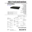
Sony HBD-E190 / HBD-E290 / HBD-E490 / HBD-E690 (serv.man2) Service Manual ▷ View online
SERVICE MANUAL
SUPPLEMENT-1
1
HBD-E190/E290/E490/E690
Ver. 1.2 2012.08
9-890-582-81
Subject: Addition of SERVICING NOTES (TROUBLESHOOTING)
File this supplement with the service manual.
Canadian Model
HBD-E190/E490
AEP Model
E Model
HBD-E190/E290/E490/E690
UK Model
HBD-E190/E290/E490
Australian Model
HBD-E190/E290/E690
Chinese Model
Taiwan Model
HBD-E290/E490
Saudi Arabia Model
Thai Model
HBD-E290/E490/E690
South African Model
HBD-E190/E290
PX Model
HBD-E290
HBD-E190/E290/E490/E690
2
SECTION 1
SERVICING NOTES
TROUBLESHOOTING
Power Check Flow (1/2)
Check that the output voltages of the switching regulator
(SWR1) are the following value.
CN301 pin 1: 12 V (A+12V)
CN301 pin 2: 12 V (UNSW12V)
CN301 pin 3: 12 V (FEUNSW12V)
CN301 pin 8: 6 V (UNSW6V)
CN301 pin 9 : 6V (FL_6V)
Check that the following fuses are not damaged.
F5301/F5303/F5304/F5305/F5306/F5307
Ye
s
Ye
s
C
heck each voltage
w
ith
re
fe
re
nce to
the
sc
hemati
c
diagrams,
and check
that ther
e is
no
pr
oblem
in them.
Check the
related IC
on
the
MB148
board.
Ye
s
C
heck
the
fo
llow
ing
pow
er
contr
ol
si
gnal
in the power on state.
(N
ormally voltage:
+3.3
V)
MB148 board
IC6301
pin
36
to
38
(PCON
T1 to
PCON
T3)
Pin 25
(PCON
T_
FL)
Pin 47
(PVDD_
CON
T)
Ye
s
The power is turned on.
A
No
Yes
Pr
otect
mode happened “PROTECT”
dis
play appear
s
on
fluor
es
cent
tube.
No
Ye
s
C
heck
that har
nes
s is
ins
er
ted nor
mally
at
CN101
Remove harness
of
CN
101, CN
4,
FFC
CN
3503.
Measure
switchi
ng
supply board CN
101 pin4
<->
pin1,
(normal voltage
>
30V)
Ye
s
Ye
s
AMP boar
d
damage.
Exchange the
complete AMP
board.
Check
that harness is
inse
rted normally at
CN
301
and
C
N
5301. When
har
nes
s
is ins
er
ted nor
m
ally, exchange
the
switching regulator (SWR1).
No
Exchange the
damaged f
us
e.
Exchange the
complete
MB148 board, when the power is not turned on,
even if
you
exchange f
us
es
.
No
Pow
er
s
upply IC
is
damaged. Exchange
the
pow
er
s
upply IC.
No
Exchange the
IC
6301.
Part No. A-1857-997-A
Description IC
R5F3650
KC
DF
B
(for
SE
RVICE
)
No
No
Ins
er
t nor
mally the har
nes
s and
pow
er
O
N
again.
No
Sw
itching s
upply
boar
d
damage. Exchange the
complete
sw
itching s
upply
boar
d.
HBD-E190/E290/E490/E690
3
Power Check Flow (2/2)
C
heck that
a
so
und is
outputted
nor
mally.
Ch
ec
k
th
at
[A
ud
io
S
et
tin
gs
]-[A
ud
io
o
ut
pu
t] in
th
e m
en
u
sc
re
en is
“Speaker
”.
C
heck
that the dr
ive
is
oper
ating
nor
m
ally.
C
heck that
each pow
er
supply
is
s
upplied to
the
audio
block.
C
heck that
a
so
und is
nor
m
ally outputted f
rom
each
sp
ea
ke
r.
Ref
er
to the
“1. Pow
er
Check
Fl
ow
” on
page
2.
Ref
er
to
the “2-1. Flow
of
dr
ive
se
ction check” on
page
7
on or
iginal
se
rvice manual.
C
heck
that a
pictur
e
is
outputted nor
mally.
C
heck that
each s
peaker
is
connected
nor
mally.
Fr
ont/C
enter
/Sur
ro
und/Subw
oof
er
C
heck
that the PWM s
ignal is
outputted
from
the
fo
llow
ing pins
.
AMP
board
IC3001
pin
39,
40,
48,
49, 42, 43, 54, 55
C
heck
that the s
ignal is
outputted
from
the
fo
llowing
pins
.
AMP board
IC3102
pin
10, 11 (S
P
FRON
T R)
pin
16, 17 (S
P
FRON
T L)
Pin 2,
3,
8,
9
(S
P
SU
BWOOFE
R)
O
ptimize the
speaker
s
ettings
.
C
heck
that the s
ignal is
outputted
from
the
fo
llowing
pins
.
AMP board
IC3302
pin 10, 11, 16, 17 (SP CENTER) pin
2,
3 (S
P
SUR R)
Pin
8, 9 (SP
SUR L)
No
No
No
No
No
No
No
No
No
Ref
er
to the
“2. Video Check
Fl
ow
” on page 4.
Per
for
m and check [
Audio
Settings
] -
[S
peaker
Settings
] - [T
es
t T
one]
in the menu
sc
re
en,
or
re
ins
er
t the s
peaker
cables
.
Exchange the
IC
3001.
Part N
o.
6-718-103-01
Description IC
TAS
5538DGGR
Exchange the
IC
3102.
Part N
o.
6-
718
-4
43
-01
Description IC
ST
A516B1
3T
R
-A
No
Exchange the
IC
3302.
Part No. 6-718-443-01 Description IC
ST
A516B1
3T
R
-A
A
Ye
s
Ye
s
Ye
s
Ye
s
Ye
s
Ye
s
Ye
s
HBD-E190/E290/E490/E690
4
Video Check Flow
C
heck
that the dr
ive
is
oper
ating
nor
mally
.
C
heck t
hat e
ac
h pow
er
s
upply
is
s
uppli
ed.
Ye
s
Ye
s
Ye
s
Ye
s
Ye
s
Ye
s
Ye
s
Ye
s
Ye
s
Ye
s
C
heck
that VIDEO
O
U
T
is
outputted
nor
mally.
C
heck
that only the
digital
output
(HDMI) is
af
fe
cted.
C
heck
that the input voltage of
the
fo
llow
ing
pin is
6
V.
MB148 boar
d
IC
705
pin
5 (
VIN)
C
heck
that the output voltage of
the
fo
llow
ing
pin is
5
V.
MB148 boar
d
IC
705
pin
4 (
VO
U
T)
Ye
s
C
heck
that the output voltage of
the
fo
llow
ing
pin is
3.3V.
MB148 boar
d
IC
704
pin4
(VO
U
T)
Check
that there are no
abnormalities
in
CN
701.
Per
for
m other
analys
es
.
C
heck
the s
ettings
on the
menu
sc
reen.
Ref
er
to the
“1. Pow
er
Check
Fl
ow
” on
page
2.
C
heck
that the input voltage
of
the
fo
llow
ing
pin is
3.3V.
MB148
boar
d
IC
705
pin1 (C
O
N
T)
Check
that there are no
abnormalities
in
J6401.
Exchange the
complete MB148
board.
Check
the solder of
J6401.
Ref
er
to
the
“1.
Pow
er
Check F
low
” on
page
2
to
check
on
p
owe
r c
on
tro
l sig
na
l fo
r P
C
ON
T_3
Ref
er
to
the “2-1. Flow
of
dr
ive s
ection
check”
on
page 7
on
or
iginal
se
rv
ice manual.
Exchange the
IC
705.
Part N
o.
6-705-337-01
Description IC
TK1115
0CS
C
L-G
C
heck
that the input voltage
of
the
fo
llow
ing
pin is
3.3V.
MB148 board
IC704
pin1 (CON
T)
Ref
er
to the
“1. Pow
er
Check
Fl
ow
” on page 2.
Exchange the
IC
704.
Part N
o.
6-702-302-01
Description IC
TK1113
3CS
C
L-G
Part N
o.
1-821-398-41
De
sc
rip
tio
n H
D
MI
CON
N
EC
TOR
(H
DMI
OUT
ARC)
Exchange the
C
N
701
N
ote: When
CN701
is
exchanged,
be
careful
of the
qual
ity of sol
deri
ng enough.
No
No
No
No
No
No
No
No
No
No
No
Display


