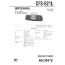
Sony CFS-B21L Service Manual ▷ View online
CFS-B21L
AEP Model
UK Model
SERVICE MANUAL
RADIO CASSETTE-CORDER
MICROFILM
Model Name Using Similar Mechanism CFS-B15
Tape Transport Mechanism Type MF-B15-117
SPECIFICATIONS
Frequency range FM : 87.6–107 MHz
MW : 531–1,602 kHz
LW : 153–279 kHz
LW : 153–279 kHz
IF FM : 10.7 MHz
MW/LW : 455 kHz
Aerials FM : Telescopic
MW/LW : Built-in ferrite bar
Recording system 4-track, 2-channel stereo
Frequency response 100-10,000Hz
Speakers Full-range : 10cm (4 inches) dia.
Frequency response 100-10,000Hz
Speakers Full-range : 10cm (4 inches) dia.
×
2,
cone type
Output Headphones jack (stereo minijack), for
16 to 68 ohms impedance headphones
Maximum power output 2.0W+2.0W
Battery life FM Recording : Sony R20P : Approx.
Battery life FM Recording : Sony R20P : Approx.
9 hours/Sony alkaline LR20 : Approx.
21 hours
Playback : Sony R20P : Approx.
6 hours/Sony alkaline LR20 : Approx.
13 hours
21 hours
Playback : Sony R20P : Approx.
6 hours/Sony alkaline LR20 : Approx.
13 hours
Power requirements 230V AC, 50Hz
6V DC, four R20 (size D) batteries
Power consumption AC 13W
Dimensions Approx. 422
Dimensions Approx. 422
×
140
×
136mm (w/h/d)
(16
5
/
8
×
5
5
/
8
×
5
3
/
8
inches) incl.
projecting parts and controls
Mass Approx. 1.9kg (4lb 3 oz) incl.
batteries
Supplied accessory Mains lead (1)
Design and specifications are subject to change without notice.
Ver 1.2 1999.12
With SUPPLEMENT-1 (9-9923-272-81)
With SUPPLEMENT-2 (9-9923-272-82)
With SUPPLEMENT-2 (9-9923-272-82)
— 2 —
TABLE OF CONTENTS
SAFETY-RELATED COMPONENT WARNING!!
COMPONENTS IDENTIFIED BY MARK
!
OR DOTTED LINE WITH
MARK
!
ON THE SCHEMATIC DIAGRAMS AND IN THE PARTS
LIST ARE CRITICAL TO SAFE OPERATION. REPLACE THESE
COMPONENTS WITH SONY PARTS WHOSE PART NUMBERS
APPEAR AS SHOWN IN THIS MANUAL OR IN SUPPLEMENTS
PUBLISHED BY SONY.
COMPONENTS WITH SONY PARTS WHOSE PART NUMBERS
APPEAR AS SHOWN IN THIS MANUAL OR IN SUPPLEMENTS
PUBLISHED BY SONY.
1.
GENERAL
··································································· 3
2.
DISASSEMBLY
2-1.
Removal of Front Cabinet ··············································· 4
2-2.
Removal of Mechanism Deck ········································· 4
2-3.
Dial Pointer Setting ························································· 5
3.
MECHANICAL ADJUSTMENTS
························· 6
4.
ELECTRICAL ADJUSTMENTS
4-1.
Tape Recoder Section ······················································ 6
4-2.
Radio Section ·································································· 7
5.
DIAGRAMS
5-1.
Circuit Board Location ···················································· 9
5-2.
IC Block Diagrams ·························································· 10
5-3.
Printed Wiring Board – Main Section – ·························· 11
5-4.
Schematic Diagram – Main Section – ····························· 13
5-5.
Printed Wiring Board and Schematic Diagram
– Tuner Section – ····························································· 16
– Tuner Section – ····························································· 16
6.
EXPLODED VIEWS
6-1.
Front Cabinet Section ······················································ 19
6-2.
Rear Cabinet Section ······················································· 20
6-3.
Mechanism Deck Section (1) ·········································· 21
6-4.
Mechanism Deck Section (2) ·········································· 22
7.
ELECTRICAL PARTS LIST
·································· 23
— 3 —
SECTION 1
GENERAL
1
FM MODE/ISS switch
2 2
(phones) jack
3
MEGA BASS button
4
VOLUME knob
5
TONE knob
6
MIC
7
ORP/BATT indicator
8
FUNCTION switch
9
BAND switch
!º
TUNING knob
!¡
PAUSE button
!™
STOP/EJECT button
!£
FF button
!¢
REW button
!∞
PLAY button
!§
REC button
1
2
3
4
5
6 7
8
9
!º
!¡
!™
!£
!¢
!∞
!§
— 4 —
SECTION 2
DISASSEMBLY
2-1.
REMOVAL OF FRONT CABINET
Note : Follow the disassembly procedure in the numerical order given.
3
+BVTP 3
×
14
2
+BVTP 3
×
14
1
battery case lid
4
Push the
EJECT button
5
front cabinet
2
Remove the mechanism deck
in the direction of the arrow.
1
+BVTP 3
×
10
2-2.
REMOVAL OF MECHANISM DECK
•
The equipment can be removed using the following procedure.
Front cabinet Mechanism Deck Main board Volume board
Retainer board Dial Pointer Bracket
Power board
Battery board
Tuner board


