Sharp VC-S2000 (serv.man2) Service Manual ▷ View online
49
VC-S2000HM
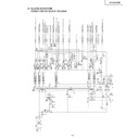
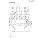
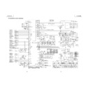
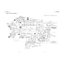
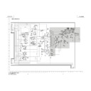
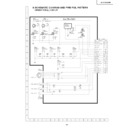
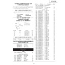
FLOW CHART NO.27 DECODER TROUBLESHOOTING
<Hi-Fi Audio Double scart>
MODE
SIG.
DECODER CIRCUIT
SELECT
INPUT SIGNAL
FLOW
SIG.
FLOW
INPUT
(switch)
OUTPUT
OUTPUT SIGNAL
(A)
Pin47 of IC701(Y/C video output)
E2(L2) video input
Front video input
→
pin7
pin28
pin13
pin25
→
E1(L1) video output
21PIN CONNECTOR
(B)
(C)
→ →
(A)
(B)
(C)
Pin58 of IC6301(Audio output L-ch)
E2(L2) audio input(L-ch)
Front audio input(L-ch)
→
pin2
pin33
pin11
pin42
→
E1(L1) audio output(L-ch)
21PIN CONNECTOR
→ →
(A)
Pin56 of IC6301(Audio output R-ch)
E2(L2) audio input(R-ch)
Front audio input(R-ch)
→
pin1
pin34
pin10
pin43
→
E1(L1) audio output(R-ch)
21PIN CONNECTOR
(B)
→
(C)
→
(A)
Tuner video output
E1(L1) video input
Pin47 of IC701(Y/C video output)
→
pin18
pin23
pin7
pin26
→
E2(L2) video output
21PIN CONNECTOR
(B)
→
(C)
→
(A)
MPX output(L-ch)
E1(L1) audio input(L-ch)
Pin58 of IC6301(Audio output L-ch)
→
pin16
pin36
pin2
pin30
→
E2(L2) audio output(L-ch)
21PIN CONNECTOR
(B)
→
(C)
→
(A)
MPX output(R-ch)
E1(L1) audio input(R-ch)
Pin56 of IC6301(Audio output R-ch)
→
pin15
pin37
pin1
pin31
→
E2(L2) audio output(R-ch)
21PIN CONNECTOR
(B)
→
(C)
→
(A)
(B)
(C)
(D)
E2(L2) video input
E1(L1) video input
Tuner video input
Front audio input(L-ch)
→
pin28
pin23
pin18
pin13
pin5
→
Pin31 of IC201
Y/C video input
(Tuner/Aux. input)
→ → →
(A)
(B)
(C)
(D)
E2(L2) audio input(L-ch)
E1(L1) audio input(L-ch)
MPX output(L-ch)
Front video input
→
pin33
pin36
pin16
pin11
pin39
→
Pin61 of IC6301
Audio input(L-ch)
→ → →
(A)
(B)
(C)
(D)
E2(L2) audio input(R-ch)
E1(L1) audio input(R-ch)
Tuner audio output
Front audioinput (R-ch)
→
pin34
pin37
pin15
pin10
pin40
→
Pin52 of IC6301
Audio input(R-ch)
→ → →
NO
NO
NO
YES
YES
YES
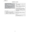
Check STBY 5V line.
Check STBY 12V line.
Check line between pins(21), (22)
of IC2501 and pins(17), (18) of
IC701.
Is voltage 5V applied to the video
section power terminal at pins(24),
(29) of IC2501?
Is voltage 12V applied to the
audio section power terminal at
pin(14) of IC2501?
Check signal line from video and
audio function logic table as shown
below.
Not output from 21pin connector in video and audio signal.
Is there SDA and SCL signal
applied to pins(21) and (22) of
IC2501?
50
VC-S2000HM
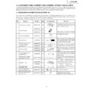
REPLACEMENT OF IC705(E
2
PROM)
Servicing precautions
When the IC705(E
2
PROM) has been replaced, make the following reprogramming.
Depending on models, the IC705(E
2
PROM) has been factory adjusted for it s memory function.
It s therefor necessary to reprogram the memory function for the model in question.
Note that the servo circuit requires readjustments for the slow and still modes.
Note that the servo circuit requires readjustments for the slow and still modes.
1. Memory function reprogramming.
1. Check the power off.(Power is standby mode)
2. Make for moment short-circuit test point(P802), located at the front side on the main PWB.
2. Make for moment short-circuit test point(P802), located at the front side on the main PWB.
Be sure that all the fluorescent display tube light up into the TEST mode.
3. Using the CHANNEL(+) AND (—) buttons, select the right function numbers from JP0 to JP39, which appear in the
fluorescent display tube, referring to the E
2
PROM map.
Press the DISPLAY button to pickup the functions(ON) and the CLEAR button to discard the functions(OFF).
DISPLAY and CLEAR buttons, are located on the remote control unit.
DISPLAY and CLEAR buttons, are located on the remote control unit.
∗
when the DISPLAY button has been pressed (ON), the memory function number starts flashing.
∗
when the CLEAR button has been pressed (OFF), the memory function number lights up.
4. Press the FF button on the remote control unit.
By doing, lower 7 of the 10 digits are displayed in hexadecimal notation.
5. Similarly to the above step 4, press the STOP button on the remote control unit.
By doing, upper 3 of the 10 digits are displayed in hexadecimal notation.
6. Example : "ON" and "OFF" are taken as "1" and "0" respectively.
The numbers JP0 to JP39 are divided into four groups and each group s setting is displayed in hexadecimal notation.
1
When the press the FF button on the remote control unit.
By doing, lower 7 of the 10 digits are displayed in hexadecimal notation.
By doing, lower 7 of the 10 digits are displayed in hexadecimal notation.
JP27 JP26 JP25 JP24
1
1
0
0
↓
C
JP23 JP22 JP21 JP20
0
0
0
0
↓
0
JP19 JP18 JP17 JP16
0
0
0
0
↓
0
JP15 JP14 JP13 JP12
0
1
0
0
↓
4
JP11 JP10 JP9 JP8
0
0
1
1
↓
3
JP7 JP6 JP5 JP4
0
0
0
0
↓
0
JP3 JP2 JP1 JP0
0
0
0
0
↓
0
2
When the press the STOP button on the remote control unit.
By doing, upper 3 in the 10 digits are displayed in hexadecimal notation from the feature function.
Also recording level preset number selected from the ten keys on the remote control unit which appear in the
fluorescent display tube, referring to the E
By doing, upper 3 in the 10 digits are displayed in hexadecimal notation from the feature function.
Also recording level preset number selected from the ten keys on the remote control unit which appear in the
fluorescent display tube, referring to the E
2
PROM map.
JP39 JP38 JP37 JP36
0
0
0
0
↓
0
JP34 JP33 JP32
0
0
0
↓
1
JP31 JP30 JP29 JP28
0
0
0
0
↓
0
51
VC-S2000HM
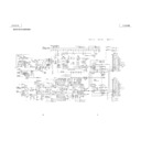
2. SETTING OF Y/C RECORD CURRENT AND HOW TO SET THE TCB CONTROL
PARAMETER.
1.Make sure that the condition of the set is POWER OFF mode.
2.Make the test point on the main PWB short-circuited condition momentarily. Or, transmit a test key (47h) from the
2.Make the test point on the main PWB short-circuited condition momentarily. Or, transmit a test key (47h) from the
remote controller.
Make sure that all the fluorescent display tubes are turned on. After that, push the MENU button of the remote
controller.
Make sure that all the fluorescent display tubes are turned on. After that, push the MENU button of the remote
controller.
3.Make sure that indication changed as the upper figure.
Input setting value to BF in turn from the data on C0. Setting value shows it in the attached table.Ten keys and an
operation key are used here.
operation key are used here.
A:PAUSE
D:STOP
B:FF
E:REC
C:REW
F:PLAY
4.Push the menu button of the remote controller again if input to BF from C0 is completed.At that time, CHECK SUM
is indicated. (It is indicated only while a menu button is being pushed.)."3AE5" is indicated when attached materials
are set up.
are set up.
<<Changing in the FIP indication>>
0:00
JP 0
C0:44
Short-circuit a test point,
and or 47h is transmitted.
and or 47h is transmitted.
MENU is transmitted from
the remote controller.
the remote controller.
ROM
ADRS DATA
C0
C1
C2
C3
C4
C5
C6
C7
C8
C9
C1
C2
C3
C4
C5
C6
C7
C8
C9
CA
Cb
CC
Cd
CE
CF
CF
44
33
34
23
13
44
33
35
33
33
44
33
45
33
23
33
34
23
13
44
33
35
33
33
44
33
45
33
23
7B
ROM
ADRS DATA
80
81
82
83
84
85
86
87
88
89
81
82
83
84
85
86
87
88
89
8A
8b
8C
8d
8E
8F
8F
00
00
00
00
00
00
40
00
00
00
00
00
00
00
00
80
00
00
00
00
00
40
00
00
00
00
00
00
00
00
80
ROM
ADRS DATA
90
91
92
93
94
95
96
97
98
99
91
92
93
94
95
96
97
98
99
9A
9b
9C
9d
9E
9F
9F
00
00
00
00
64
64
64
65
65
65
65
65
65
04
04
04
00
00
00
64
64
64
65
65
65
65
65
65
04
04
04
ROM
ADRS DATA
A0
A1
A2
A3
A4
A5
A6
A7
A8
A9
A1
A2
A3
A4
A5
A6
A7
A8
A9
AA
Ab
AC
Ad
AE
AF
AF
05
05
05
05
05
05
81
81
81
81
81
81
05
05
05
05
05
81
81
81
81
81
81
FF
FF
FF
FF
FF
FF
FF
ROM
ADRS DATA
B0
B1
B2
B3
B4
B5
B6
B7
B8
B9
B1
B2
B3
B4
B5
B6
B7
B8
B9
BA
Bb
BC
Bd
BE
BF
BF
FF
FF
FF
FF
FF
FF
FF
FF
FF
FF
FF
FF
FF
FF
FF
FF
FF
FF
FF
FF
FF
FF
FF
FF
FF
FF
FF
FF
FF
FF
FF
ROM
ADRS DATA
d0
d1
d2
d3
d4
d5
d6
d7
d8
d9
d1
d2
d3
d4
d5
d6
d7
d8
d9
dA
db
dC
dd
dE
dF
dF
7B
7B
4B
4B
4B
7B
4B
4B
4B
00
04
04
04
08
08
08
08
08
08
04
04
04
08
08
08
08
08
08
0C
ROM
ADRS DATA
E0
E1
E2
E3
E4
E5
E6
E7
E8
E9
E1
E2
E3
E4
E5
E6
E7
E8
E9
EA
Eb
EC
Ed
EE
EF
EF
0C
20
20
20
30
30
30
20
20
20
30
30
30
20
20
30
30
30
20
20
20
30
30
30
2E
2E
2E
2E
2E
ROM
ADRS DATA
F0
F1
F2
F3
F4
F5
F6
F7
F8
F9
FA
Fb
F1
F2
F3
F4
F5
F6
F7
F8
F9
FA
Fb
FC
Fd
FE
EF
EF
3E
3E
3E
2E
2E
2E
3E
3E
3E
2E
2E
2E
3E
3E
3E
3E
3E
2E
2E
2E
3E
3E
3E
2E
2E
2E
3E
3E
3E
00
ROM
ADRS DATA
00
01
02
03
04
05
06
07
08
09
01
02
03
04
05
06
07
08
09
0A
0b
0C
0d
0E
0F
0F
40
40
00
80
80
00
40
40
00
40
40
00
80
80
00
80
40
00
80
80
00
40
40
00
40
40
00
80
80
00
80
ROM
ADRS DATA
10
11
12
13
14
15
16
17
18
19
11
12
13
14
15
16
17
18
19
1A
1b
1C
1d
1E
1F
1F
80
64
64
64
65
65
65
04
04
04
05
05
05
00
00
00
64
64
64
65
65
65
04
04
04
05
05
05
00
00
00
ROM
ADRS DATA
20
21
22
23
24
25
26
27
28
29
21
22
23
24
25
26
27
28
29
2A
2b
2C
2d
2E
2F
2F
00
00
00
00
00
00
00
00
00
00
00
00
00
00
00
00
00
00
00
00
00
00
00
00
00
00
00
00
00
00
00
ROM
ADRS DATA
30
31
32
33
34
35
36
37
38
39
31
32
33
34
35
36
37
38
39
3A
3b
3C
3d
3E
3F
3F
00
7B
7B
7B
4B
4B
4B
4B
4B
4B
7B
7B
4B
4B
4B
4B
4B
4B
00
04
04
04
08
08
04
04
04
08
08
ROM
ADRS DATA
40
41
42
43
44
45
46
47
48
49
41
42
43
44
45
46
47
48
49
4A
4b
4C
4d
4E
4F
4F
04
08
08
08
08
08
08
08
08
08
08
08
08
0C
0C
0C
08
0C
0C
0C
20
20
20
30
20
20
30
ROM
ADRS DATA
50
51
52
53
54
55
56
57
58
59
51
52
53
54
55
56
57
58
59
5A
5b
5C
5d
5E
5F
5F
30
30
30
30
30
20
20
20
30
30
30
30
30
30
30
30
30
30
20
20
20
30
30
30
30
30
30
2E
2E
2E
ROM
ADRS DATA
60
61
62
63
64
65
66
67
68
69
61
62
63
64
65
66
67
68
69
6A
6b
6C
6d
6E
6F
6F
2E
3E
3E
3E
3E
3E
3E
2E
2E
2E
3E
3E
3E
3E
3E
3E
3E
3E
3E
3E
3E
3E
2E
2E
2E
3E
3E
3E
3E
3E
3E
ROM
ADRS DATA
70
71
72
73
74
75
76
77
78
79
71
72
73
74
75
76
77
78
79
7A
7b
7C
7d
7E
7F
7F
2E
2E
2E
3E
3E
3E
3E
3E
3E
2E
2E
3E
3E
3E
3E
3E
3E
00
00
00
00
80
00
00
00
00
00
80
00
00
CHECK SUM CODE(77EH)
VC-S2000GM
3AE5
VCS2000HM
3AE5
E2PROM SETTING DATA FOR Y/C DATA
52
VC-S2000HM
ROM MAP
MODEL
S2000HM
YC DATA SUM
3AE5
REC CURRENT DATA SUM
IC701
iX1589GE
JP39
A.DUB
1
JP38
SLOW ATR
0
JP37
S.SIMPLE PB
0
JP36
NTPB
1
JP35
NTSC SKEW
0
JP34
HEAD 2
0
JP33
HEAD 1
1
JP32
HEAD 0
0
JP31
GAMMA
0
JP30
LOW PWR 5Min
0
JP29
POSI84
1
JP28
R/C CODE (1/2)
0
JP27
DNR
1
JP26
POST CODE
1
JP25
SAT CTL
1
JP24
AV LINK/16:9
1
JP23
Hi-Fi
1
JP22
SORT/CLOCK
1
JP21
DECODER
1
JP20
SURROUND
0
JP19
IGR
0
JP18
NICAM
1
JP17
G-CODE1
1
JP16
G-CODE0
1
JP15
EP(Tape Speed 1)
1
JP14
LP(Tape Speed 0)
0
JP13
F-AV
1
JP12
2 SCART
1
JP11
RF OUTPUT OFF
0
JP10
TUNER2
1
JP9
TUNER1
0
JP8
TUNER0
0
JP7
SYSTEM1
0
JP6
SYSREM0
0
JP5
INT-SAT
0
JP4
LOW POWER
1
JP3
OEM
0
JP2
VPS/PDC
1
JP1
COLOUR1
0
JP0
COLOUR0
0
DISPLAY
922FE7B414
0:LIGHT UP
1:FLASHING

