Sharp VC-MH835 (serv.man18) User Manual / Operation Manual ▷ View online
5
www.sharp.co.uk/support
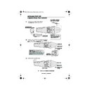
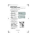
INSTALLING YOUR VCR
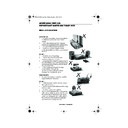
CONNECTING THE CABLES
✔
The VCR is correctly connected.
LINE1(I)IN
/OUT
SON/VIDEO
(L1/I)
A2230
LINE2(II)IN/DECODER CANAL PLUS/L2(II)
AUDIO OUT
SORTIE SON
L G
R D
AERIAL IN
ENTREE ANTENNE
AERIAL OUT
SORTIE ANTENNE
LINE1(I)IN
/OUT
SON/VIDEO
(L1/I)
A2230
LINE2(II)IN/DECODER CANAL PLUS/L2(II)
AUDIO OUT
SORTIE SON
L G
R D
AERIAL IN
ENTREE ANTENNE
AERIAL OUT
SORTIE ANTENNE
LINE1(I)IN
/OUT
SON/VIDEO
(L1/I)
A2230
LINE2(II)IN/DECODER CANAL PLUS/L2(II)
AUDIO OUT
SORTIE SON
L G
R D
AERIAL IN
ENTREE ANTENNE
AERIAL OUT
SORTIE ANTENNE
EXISTING AERIAL
OR CATV CABLE
OR CATV CABLE
Optional:
Connect your
Satellite receiver or decoder to
the VCR using a scart lead to
the VCR using a scart lead to
LINE 2 IN/DECODER
socket on the VCR.
Connect your existing aerial cable to
the
the
AERIAL IN
socket on your VCR.
DECODER UNIT
OR SATELLITE SYSTEM
OR SATELLITE SYSTEM
1
2
3
Connect your TV to the VCR using the supplied RF
connection cable, i.e. connect the VCR
connection cable, i.e. connect the VCR
AERIAL
OUT
socket to the TV
AERIAL IN
socket.
Connect the VCR to the mains.
SCART LEAD
(Not Supplied)
SCART LEAD
AERIAL IN
AERIAL OUT
RF CONNECTION
CABLE
CABLE
AERIAL IN
AERIAL OUT
RF CONNECTION
CABLE
BACK OF
TELEVISION
Optional
SCART (not supplied). If you
have a scart lead connect it to your TV and
LINE 1 IN/OUT
socket on the VCR.
- The advantage of a Scart connection is
improved picture and sound quality during
playback.
improved picture and sound quality during
playback.
TINS-A082UMN1.book Page 5 Monday, November 4, 2002 2:33 PM
6
www.sharp.co.uk/support
INSTALLING YOUR VCR
INSTALLATION OF A SATELLITE RECEIVER/CABLE
BOX
BOX
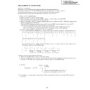
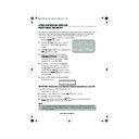
If you have a satellite receiver connected to your VCR you can automatically install the
satellite channels using the following installation procedure.
The installation procedure for cable boxes is the same as for satellite receivers (for cable box
connections refer to your cable box manual).
Follow steps 1-4 below before continuing with the installation:
1.
Connect your satellite receiver to the VCR as previously shown.
2.
Place the satellite receiver near the VCR (ideally on the top).
3.
Ensure the receiver is not in any special mode and switched on.
4.
Ensure all the channels you wish to be tuned are within channel positions 1-199 on your
satellite receiver (not applicable to digital). The VCR will only tune up to the first 199
channels - refer to your satellite receiver operation manual for instructions on moving
channels.
•
The satellite channels can now be tuned in as part of the auto-installation procedure.
You will be prompted for further information from the on-screen displays.
•
SHARP cannot guarantee this feature will work with all satellite receivers and cable
boxes.
All information relevant to satellite receiver control will display this symbol.
TINS-A082UMN1.book Page 6 Monday, November 4, 2002 2:33 PM
7
www.sharp.co.uk/support
INSTALLING YOUR VCR
AUTO TUNING
PROCEDURE
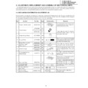
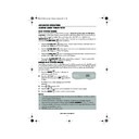
This model automatically tunes the TV channels for your area, then using Teletext information
sorts the TV channels into a standard order and sets the clock. If the VCR has not previously
been tuned-in, instructions will be given on screen to guide you through this procedure.
sorts the TV channels into a standard order and sets the clock. If the VCR has not previously
been tuned-in, instructions will be given on screen to guide you through this procedure.
1.
Ensure your VCR is still in the STANDBY mode.
2.
Switch on the
TV
.
3.
Select the next available or unused channel on your TV, this will become the dedicated
video channel.
video channel.
Example of
TV channels
TV channels
4.
Press the
STOP
button. The VCR will
search and display an ideal RF channel.
Wait for the flashing channel number to appear
on the VCR display, this number will be between
21 and 69.
Wait for the flashing channel number to appear
on the VCR display, this number will be between
21 and 69.
•
If you are connected via a scart lead, go to step 6.
CAUTION:
5.
Tune the selected channel on your TV.
(Refer to your TV manual for
instructions on how to tune in your TV).
(Refer to your TV manual for
instructions on how to tune in your TV).
Store this as your VCR channel.
NOTE:
6.
Press the
SET
button to store the RF channel setting and continue with the
installation.
See next page to continue
If the clear button is pressed at this point it will not allow the TV to be tuned to the VCR. Refer
to RF through ON/OFF on page 48.
to RF through ON/OFF on page 48.
If the AUTO INSTALLATION screen doesn’t appear when you switch on your VCR or you wish
to reset your VCR and start the installation again, refer to
to reset your VCR and start the installation again, refer to
VCR RESET
at the back of the
book.
1 = BBC1
4 = Channel 4
2 = BBC2
5 = Channel 5
3 = ITV
? = VCR
AUT O
I NS T AL L AT I ON
P R E S S
S E T
K E Y
T O S T AR T .
S E T
: E N T E R
ME NU : E X I T
Blue
background
with
White Text
TV SCREEN
SET
EXAMPLE
TINS-A082UMN1.book Page 7 Monday, November 4, 2002 2:33 PM
8
www.sharp.co.uk/support
INSTALLING YOUR VCR
AUTO TUNING CONTINUED
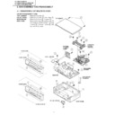
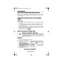
7.
Ensure your Aerial/Scart cables are
connected to your VCR and then
press the
SET
button to confirm.
8.
SAT CONTROL
will be highlighted. If
you
do
not
have a satellite receiver
connected to the VCR leave SAT
CONTROL set to OFF and press the
SET
button.
The VCR will attempt to copy the TV
preset list (NexTView, Smart Link, Easy
Link and Megalogic compatible TV’s
only). During the copying process the
display will show the TV presets that
are being copied. If the VCR is
unable to copy the TV preset list the
terrestrial channels will be
automatically installed. (Auto install
may take a few minutes.)
PLEASE CONTINUE WITH
YOUR INSTALLATION ON
PAGE 10!
YOUR INSTALLATION ON
PAGE 10!
SATELLITE RECEIVER INSTALLATION
If you
do
have a satellite receiver
connected to the VCR continue
from Point 9 on the next page.
SET
P L E A S E
B E
S UR E
T H E
A E R I A L / S CAR T
CAB L E I S
CONN E C T E D T O YOUR V CR .
P R E S S
S E T
T O CON T I NU E
S E T
: E N T E R ME NU : E X I T
8.
1
CH 2 2
AU T OMA T I C
T UN I NG .
P L E A S E WA I T .
ME NU : E X I T
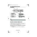
Button positions for your reference.
REMOTE CONTROL
7.
S A T
R E C E I V E R
S A T CON T RO L ON
O F F
: CHANGE
S E T
: E N T E R ME NU : E X I T
SET
SET
TINS-A082UMN1.book Page 8 Monday, November 4, 2002 2:33 PM
Display

