Sharp VC-MH703 Service Manual ▷ View online
2
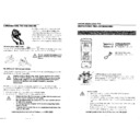
When servicing the unit with power on, be careful of the section outlined in white.
This is the primary power circuit which is live.
When checking the solder side in the tape travel mode, make sure that the tape has been loaded and then turn over
the PWB with due care to the primary power circuit.
Make readjustment, if needed after replacement of part, with the mechanism and its PWB in position in the main
frame.
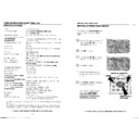
(1) Start and end sensors: Q701 and Q702
Insert the sensor’s projection deep into the upper hole of the holder. Referring to the PWB, fix the sensors tight
enough.
When replacing the mechanism on the PWB care should be taken that the sensors locate into the mechanism
holder.
enough.
When replacing the mechanism on the PWB care should be taken that the sensors locate into the mechanism
holder.
(2) Photocoupler: IC901
Refer to the symbol on the PWB and the anode marking of the part.
(3) Cam switches A and B: D708 and D705.
Adjust the notch of the part to the white marker symbol on the PWB. The part must be flat to the PWB.
(4) Take-up and supply sensors: D711 and D712.
Be careful not to confuse the setting direction of these parts in reference to the symbols on the PWB. The part
must be flat to the PWB.
must be flat to the PWB.
PRECAUTIONS IN PART REPLACEMENT
3
SPECIFICATIONS
Format: VHS PAL standard
Video recording system: Two rotary heads, helical scan system
Video signal: PAL colour and I signals, 625 lines
Recording/playing time: 240 min max. with an E-240 tape SP
480 min max. with an E-240 tape LP
Tape width: 12.7mm
Tape speed: 23.39 mm/s SP
11.70 mm/s LP
Antenna: 75 ohm unbalanced
Receiving channel: UHF Channel E21-E69;
VHF Channel E2 - S41 (VC-MH713LM only)
RF converter output signal: UHF Channel E21-E69 (Preset to CH E36)
Power requirement: AC230V-240V, 50Hz
Power consumption: Approx. 15W (AC230V/50Hz) and 3W max. at stand-by mode
Operating temperature: 5
°C to 40°C
Storage temperature: –20
°C to 55°C
Weight: Approx. 3.2 kg
Dimensions: 360 mm (W) x 289 mm (D) x 93 mm (H)
(14-3/16" x 12-1/32" x 3-21/32")
VIDEO
Input: 1.0 Vp-p, 75 ohm
Output: 1.0 Vp-p, 75 ohm
S/N ratio: 48 dB (SP mode)
Horizontal resolution: Approx. 260 lines (SP mode with Super Picture)
AUDIO 0 dBs = 0.775 Vrms
Input: Line1: –3.8 dBs, 10k ohm
Line2: –3.8 dBs, 10k ohm
Line3: –3.8 dBs, 10k ohm
Line3: –3.8 dBs, 10k ohm
Output: Line1: –3.8 dBs, 1k ohm
Line2: –3.8 dBs, 1k ohm
REAR RCA:- -3.8dBs, 1k ohm
REAR RCA:- -3.8dBs, 1k ohm
S/N ratio: 46 dB min. (SP mode)
Frequency response: 80 Hz ~ 10 kHz (SP mode)
80 Hz ~ 5 kHz (LP mode)
Hi-Fi dynamic range: 85dB TYP
HI-FI WOW and flutter: 0.005% Max
Hi-Fi Frequency responce: 20Hz - 20kHz
Hi-Fi Distortion: 0.5% Max
Hi-Fi closs talk (at 1kHz): 55 dB min.
Accessories included: 75 ohm coaxial cable
Operation manual
Infrared remote control
Batteries
Infrared remote control
Batteries
As part of our policy of continuous improvement, we reserve
the right to alter design and specifications without notice.
the right to alter design and specifications without notice.
Note: The antenna must correspond to the new standard DIN 45325
(IEC 169 - 2) for combined UHF/VHF antenna with 75 ohm connector.
4
ROM MAP
MODEL
VC-MH713LM
blank
blank
EP n * *
NTSC Luminance level
EP n * *
NTSC Chrominance level
SP n * *
NTSC Luminance level
SP n * *
NTSC Chrominance level
LP p * *
PAL Luminance level
LP p * *
PAL Chrominance level
blank
blank
SP p * *
PAL Luminance level
SP p * *
PAL Chrominance level
"0"
fixed
JP39
A.DUB
JP38
NOT SLOW ATR
JP37
SQ PB
JP36
NTSC PB
JP35
NTSC SKEW
JP34
HEAD2
JP33
HEAD1
JP32
HEAD0
JP31
GAMMA correction
JP30
L/P-5 min
JP29
84 channel
JP28
R/C CODE 1
JP27
DNR
JP26
POST CODE
JP25
SAT CTL
JP24
AV LINK / 16 x 9
JP23
Hi-Fi
JP22
SORT/CLOCK
JP21
DECODER
JP20
SURROUND
JP19
IGR
JP18
NICAM
JP17
G-CODE1
JP16
G-CODE0
JP15
OEM
JP14
LP mode
JP13
F-AV
JP12
2 SCART
JP11
No RF OUT
JP10
TUNER2
JP 9
TUNER1
JP 8
TUNER0
JP 7
SYSTEM1
JP 6
SYSTEM0
JP 5
X 380 FF/REW
JP 4
LOW POWER
JP 3
N/A
JP 2
VPS/PDC
JP 1
COLOUR 1
JP 0
COLOUR 0
DISPLAY IN HEXADECIMAL
NOTATION
DISPLAY IN HEXADECIMAL
NOTATION
12A0
0:LIGHT UP
1:FLASHING
VC-MH713HM(G)
VC-MH703HM(G)
--
0
7
0
7
3
3
--
4
4
0
7
0
7
3
3
--
4
4
0
0
0
0
0
0
0
0
0
0
1
0
0
0
0
0
0
0
0
0
1
0
1
0
0
0
0
0
0
0
0
0
1
0
1
0
0
1
1
1
0
1
1
1
0
1
1
1
1
1
0
0
0
0
1
1
0
0
0
1
0
0
0
0
0
0
0
0
0
0
--
0
7
0
7
3
3
--
4
4
0
7
0
7
3
3
--
4
4
0
0
0
0
0
0
0
0
0
0
1
0
0
0
0
0
0
0
0
0
1
0
1
0
0
0
0
0
0
0
0
0
1
0
1
0
0
1
1
1
0
1
1
1
0
1
1
1
1
1
0
1
0
1
0
0
0
0
0
0
0
0
0
0
0
0
0
0
0
0
--
0
7
0
7
3
3
--
4
4
0
7
0
7
3
3
--
4
4
0
0
0
0
0
0
0
0
0
0
1
0
0
0
0
0
0
0
0
0
1
0
1
0
0
0
0
0
0
0
0
0
1
0
1
0
0
1
1
1
1
1
1
0
1
1
1
1
1
0
0
1
1
0
0
0
0
0
1
1
0
0
0
0
0
0
0
0
0
0
070733
440020
0A77300
440020
0A77300
070733
440020
0A77400
440020
0A77400
070733
440020
0A77300
440020
0A77300
5
DESCRIPTION
PART CODE
REF NO
713HM
713LM
703HM
CODE
★
MAIN UNIT
DUNTK5886TEV3
-
1
N/A
1
-
-
MAIN UNIT
DUNTK5886TEVE
-
N/A
N/A
1
-
-
PARTS REPLACEMENT
Parts marked with "
" are important for maintaining the safety of
the set. Replace these parts with only those specified
"HOW TO ORDER REPLACEMENT PARTS"
Contact your nearest SHARP Parts Distributor.
For location of SHARP Parts Distributor.
Call SHARP Manchester on (0161) 205 7531(0870) 600 0271
To have your order filled promptly and correctly, please supply the
following informations.
1. MODEL NUMBER
2. REF. NO
3. PART CODE
4. DESCRIPTION
5. PRICE CODE
PRINTED WIRING BOARD ASSEMBLIES
(NOT REPLACEMENT ITEM)
HOW TO IDENTIFY CHIP
TRANSISTORS AND
DIODES BY ITS MARKING
(1) Base/Input
(2) Emitter/Ground
(3) Collector/Output
MARK
★: SPARE PARTS-DELIVERY SECTION
Marking
Fig. 1
(3)
(1)
(2)
PACKAGE MARKING
PARTS CODE
TYPE MARKING
PARTS CODE
TYPE
FIG 1.
6A
VSUN2111///-1*
PNP
14
VSDTA114EK/-1*
PNP
FIG 1.
6B
VSUN2112///-1*
PNP
15
VSDTA124EK/-1*
PNP
FIG 1.
6C
VSUN2113///-1*
PNP
16
VSDTA144EK/-1*
PNP
FIG 1.
8A
VSUN2211///-1*
NPN
24
VSDTC114EK/-1*
NPN
FIG 1.
8B
VSUN2212///-1*
NPN
25
VSDTC124EK/-1*
NPN
FIG 1.
8C
VSUN2213///-1*
NPN
26
VSDTC144EK/-1*
NPN
FIG 1.
FQ
VS2A1037KQ-1
BQ
VS2SC2412KQ-1
PARTS LIST
DUNTK5886TEV3 (VC-MH713HM / VC-MH703HM)
DUNTK5886TEVE(VC-MH713LM)
DESCRIPTION PART CODE REF NO
713HM
713LM 703HM
CODE
★
PWB DUNTK5903TEV2
-
1
1
1
AN V
SWITCH QSW-K0097GEZZ
SW884
1
1
N/A
AB J
SWITCH QSW-K0097GEZZ
SW890
N/A
N/A
1
AB J
OPERATE PWB
TUNERS
DESCRIPTION
PART CODE
REF NO
713HM
713LM
703HM
CODE
★
TUNER VTUATMCB2-102 TU1551
1
N/A
1
BC
U
TUNER VTUATMDG2-801
TU1551
N/A
1
N/A
BC
U
MISCELLANEOUS
DESCRIPTION
PART CODE
REF NO
713HM
713LM
703HM
CODE
★
TOP CAB SCREW BLK
LX-HZ3097GEFF
-
1
1
1
AA
U
SCREW
XJSSF30P10000 - N/A
1
N/A
AA
U

