Sharp VC-MH64HM (serv.man9) Service Manual / Technical Bulletin ▷ View online
Sharp Electronics (UK) Limited
Originator AvW Supervisor Approval Date / / Reference TB-T9701015
Revision
White – Carry out as required, Yellow – Carry out as required and whenever the unit comes in for service, Red – Carry out on all units
VCR970502
Month of Issue: May 1997
Classification: White
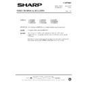
VIDEO TECHNICAL BULLETIN
Page 1 of 1
MODELS
VCM23HM
VCM24HM
VCM25HM
VCMH54HM
VCMH64HM
SYMPTOM Tape creasing, which may be intermittent.
CAUSE
AC head tilt adjustment incorrect.
ACTION
In the event of customer complaint of tape creasing or damage, the tape path must
be carefully checked as follows.
be carefully checked as follows.
1. Insert a known good E180 cassette, which has been rewound to the start. Press
RECORD and wait ten seconds before inspecting the tape transport. A bright light
is useful while carrying out this procedure.
is useful while carrying out this procedure.
2. In the event of the tape becoming visually damaged along its lower edge, between
the reverse guide and the cassette shell, the AC head is probably adjusted
correctly. This phenomenon is usually caused by the reverse guide height being
set too high. Adjust as indicated in the service manual.
correctly. This phenomenon is usually caused by the reverse guide height being
set too high. Adjust as indicated in the service manual.
3. Observe the tape as it passes over the fixed guide. The lower flange should just
be visible and the tape should not be attempting to ride over it. No wrinkles should
be visible as the tape travels over the surface of the guide.
be visible as the tape travels over the surface of the guide.
4. If the tape path is not as described in 2. above, and it is attempting to, or has
succeeded in riding over the lower flange, the AC head has excessive tilt. Using a
non-magnetic screwdriver, slowly turn the tilt adjustment screw (front of AC
head) counterclockwise until the tape path is correct at this point.
non-magnetic screwdriver, slowly turn the tilt adjustment screw (front of AC
head) counterclockwise until the tape path is correct at this point.
5. If the tape path at the fixed guide is good, as described in 2. above, proceed to
inspecting the tape path between the capstan/pinch roller and the reverse guide.
This should be carried out while viewing the tape from the rear of the VCR.
This should be carried out while viewing the tape from the rear of the VCR.
6. The tape between the capstan/pinch roller and reverse guide should be flat and
free from kinks/wrinkles. A useful check for this is to observe the reflections from
the tape surface. Assuming that the tape at the fixed guide is now correct, any
creases or damage to the
the tape surface. Assuming that the tape at the fixed guide is now correct, any
creases or damage to the
top edge of the tape is due to excessive backward
tilt (over correction from step 3.) or is the
original complaint, if the tape path in 2.
was good.
7. Verify that the tape is travelling smoothly over the fixed guide, capstan/pinch roller
and reverse guide and is returning to the cassette shell in good condition. There
should be between 0.3 and 0.5mm of the control track head visible at the bottom of
the AC head.
should be between 0.3 and 0.5mm of the control track head visible at the bottom of
the AC head.
8. Check the audio playback quality using a commercially available test tape.
Important Note
It is recommended to adjust the screws in very small steps, waiting for a few seconds between each
step to allow the tape to ‘ride’ to its new position. No more than one full turn should be required.
step to allow the tape to ‘ride’ to its new position. No more than one full turn should be required.
Display

