Sharp PZ-50HV2E (serv.man9) Service Manual ▷ View online
40
PZ-50HV2, PZ-50HV2E
PZ-50HV2U
PZ-50HV2U
Number
of
Blinks
P.D. Point in
Operation
Error Point
Possible Part of Error
Circuit State
Operation
P.D. Circuit
Diagnosis Condition
1
Y
DRIVE
IC22
0
6, IC22
14
(Pulse module), IC22
03, IC22
0
4
,
IC22
12, IC22
13, IC22
13, IC22
17, R22
0
9
K22
11
Lo
VCP OCP
2
Y
DC DC
VOFS D/D CONV. BLOCK (Y DRIVE Assy)
IC2
7
02, IC
2
7
0
9, IC2
7
15
K
2
7
12
Lo
VOFS OVP
VOFS D/D CONV. BLOCK (Y DRIVE Assy)
IC2
7
0
1,
IC2
7
02, IC
2
7
0
9, IC2
7
15
K
2709
L
o
VOFS UVP
Drive section (control signal, output elements etc.) in
normal operation
Q22
11
, Q22
12, R22
7
7, IC22
0
8, IC22
10
VOFS D/D CONV. BLOCK in normal operation
VH D/D CONV. BLOCK (Y DRIVE Assy)
IC2
7
12, IC2
7
16
K
2
7
19
Lo
VH OVP
VH D/D CONV. BLOCK (Y DRIVE Assy)
IC2
7
11
, IC2
7
12, IC2
7
16
K2
7
18 Lo
VH UVP
Drive section (control signal, output elements etc.) in
normal operation
SCAN (A), (B) Assy
SCAN IC
VH D/D CONV. BLOCK in normal operation
IC
5V D/D CONV. BLOCK (Y DRIVE Assy)
IC
2
7
0
4, IC2
7
0
6, IC2
7
17
SCAN Assy in normal operation
SCAN (A), (B) Assy
Y DRIVE Assy
SCAN IC
K2
7
13 Lo
IC
5V UVP
IC
5V D/D CONV. BLOCK in normal operation
IC
5V D/D CONV. BLOCK (Y DRIVE Assy)
IC
2
7
0
4, IC2
7
0
6, IC2
7
17
SCAN Assy in normal operation
3
X
DC DC
VRN D/D CONV. BLOCK (X DRIVE Assy)
IC3
7
02, IC3
7
12
K
3708
L
o
VRN OVP
VRN D/D CONV. BLOCK (X DRIVE Assy)
IC3
7
0
1,
IC3
7
02, IC3
7
12
K
3705
L
o
VRN UVP
Drive section (control signal, output elements etc.) in
normal operation
X DRIVE Assy
Q3
12
2
VRN D/D CONV. BLOCK in normal operation
4
X
DRIVE
X DRIVE Assy
IC32
0
0, IC32
0
1 (pulse module), IC3
103, IC3
10
4,
IC3
10
6, IC3
10
7, IC3
11
0, IC3
11
3, R3
10
9
K3
103 Lo
VCP OCP
Q3
12
2
K
3
102 Lo
VRN OCP
5
PS
X DRIVE Assy
IC32
0
0, IC32
0
1 (Pulse module)
When P4 connector disconnected, P.D. does not occur
Y DRIVE Assy
IC22
0
6, IC22
14
(Pulse module)
When P3 connector disconnected, P.D. does not occur
MX AUDIO Assy
IC860
1
(Audio IC)
When P6 connector disconnected, P.D. does not occur
When pin 5 of P2 connector disconnected, P.D. does
not occur
SW POWER SUPPLY Module
SW POWER SUPPLY Module
When the voltage is not output even if P4, P3 and P6
connectors disconnected
6
ADR
ADDRESS CONNECT A~D Assy
ADDRESS CONNECT A - D Assy,
RESONANCE Assy,
D/D CONV. BLOCK (DIGITAL VIDEO Assy)
Disconnect D8 - D15 connectors
7
ADR K
RESONANCE Assy
TCP damage of IC6704 (ICP), disconnect D16 and
D17 connectors, panel microcomputer is defective,
outside Flash ROM of the panel microcomputer is
defective.
8
DIGITAL
DC DC
D/D CONV. BLOCK (DIGITAL VIDEO Assy)
IC1901
K1
9
0
1 L
o
5.
0V OVP
ADR. PD
ADR. K. PD
K
19
02 Lo
5.
0V UVP
D/D CONV. BLOCK (DIGITAL VIDEO Assy)
IC1901
K
19
03 Lo
3.3V OVP
K
19
0
4
Lo
3.3V UVP
D/D CONV. BLOCK (DIGITAL VIDEO Assy)
IC1901
K
19
0
5
Lo
2.
5V OVP
K
19
0
6
Lo
2.
5V UVP
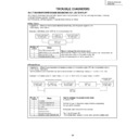
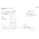
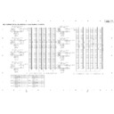
Diagnosis of the error point in the various protection circuit (P.D. circuit) operation (Red LED blinks)
Note: About PS PD
The condition that Red LED blinks five times
(power supply PD)
1
When the internal protection circuit of SW
POWER SUPPLY Module worked
2
When a microcomputer was not able to
identify the PD point
↓
Being careful because the protection circuit
of SW POWER SUPPLY Module cannot
conclude that worked.
41
PZ-50HV2, PZ-50HV2E
PZ-50HV2U
PZ-50HV2U
AC IN
100 - 240V
Power Factor
Control
VSUS DC/DC
Converter
VOFS DC/DC
Converter
VADR DC/DC
Converter
6.5V DC/DC
Converter
(6.5V, 13.5V, -9V)
15V DC/DC
Converter
(15V, 12V)
ST-BY
Power Supply
STB5V
+B395V
VSUS
13.5V
12V
-9V
VOFS
-45V
VH DC/DC
Converter
VH
130V
IC5V, VF12V
DC/DC
Converter
IC5V
VF12V
VADR
61V
VRN DC/DC
Converter
VRN
-300V
225V
SW POWER SUPPLY MODULE
Y DRIVE ASSY
X DRIVE ASSY
15V DC/DC
Converter
(5V, 3.3V, 2.5V)
3.3V
2.5V
2.5V
5.0V
DIGITAL VIDEO ASSY
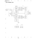
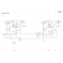
Block diagram for Power supply section
Supplementary information
1. Power on/off switch for the large-signal system (SW102)
Function: Only the power for the small-signal system
Function: Only the power for the small-signal system
Usage:
Supplementary information:
3. Temperature compensation of the VOFS voltage for
Function: Control the power supply voltage mentioned
above according to temperature. (Temperature
compensation works so that the voltage is
lowered on the lower- temperature side, and is
raised on the higher-temperature side.)
compensation works so that the voltage is
lowered on the lower- temperature side, and is
raised on the higher-temperature side.)
Purpose: To improve the yield by compensating the
temperature characteristics of the panel.
Supplementary information:
For this model, temperature compensation is
perform-ed only for the VOFS voltage, and not for
the VSUS voltage, and it is controlled by
software.
perform-ed only for the VOFS voltage, and not for
the VSUS voltage, and it is controlled by
software.
4. When a fuse blows
• If a fuse blows, never turn the power on again only after
• If a fuse blows, never turn the power on again only after
replacing the fuse. (In most cases, the fuse itself did not
have any problem. So as long as factors of overcurrent
have not been removed, chances of destruction increase
every time the power is turned on. In the worst case,
about a dozen parts may be destroyed.)
have any problem. So as long as factors of overcurrent
have not been removed, chances of destruction increase
every time the power is turned on. In the worst case,
about a dozen parts may be destroyed.)
• Principally, the whole power-supply module must be
replaced.
5. Voltage adjustment of the panel drive
As this model employs the electronic VR system for the
VSUS and VOFS voltages, and as the voltage-adjustment
data are stored in the DIGITAL assembly, voltage
adjustment of the panel drive is not necessary when the
power-supply modules are changed. (For VADR, VH, and
VRN, adjustments with semifixed VR controls are
necessary.)
For this model, as the power-supply block has been
developed and designed by an outside vendor, at the point
you know which module is a cause of failure (through
diagnosis described elsewhere in this manual), change the
corresponding modules, and do not diagnose or repair the
module.
Similarly, the switches and the semifixed VRs inside the
power-supply module must not be adjusted without a
special reason.
2. 200V AC power-down switch (SW101)
Function: While 200V AC voltage is applied, operation of
Function: While 200V AC voltage is applied, operation of
the PD circuit is turned on and off (ON when the
switch is set to 100V AC, and OFF when the
switch is set to 200V AC).
switch is set to 100V AC, and OFF when the
switch is set to 200V AC).
Setting:
For the PU model only, the switch is set to 100V,
and for other models, it is set to 200V.
and for other models, it is set to 200V.
1
Confirm that this unit is the standby state.
2
Transmit RS-232C command "DRF."
3
Turn the power supply ON by remote control unit, side
key or command "PON."
key or command "PON."
∗
Display

