Sharp PZ-50HV2E (serv.man8) Service Manual ▷ View online
19
PZ-50HV2, PZ-50HV2E
PZ-50HV2U
PZ-50HV2U
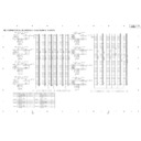
3. Adjustment and Setting Item of the Plasma Display
Display example of the eleventh page
1
2
3
4
5
6
7
8
9
2
3
4
5
6
7
8
9
10
11
12
13
14
15
16
17
18
11
12
13
14
15
16
17
18
MNTR
1
1 / 1 3
PUT1 No S I G
N
I
V5 0
0 2
WB
MNTR V6 0
0 1
WB
MNTR PC
0 1
WB
MNTR R H
2 5 5
I GH1
MNTR R H
2 5 5
I GH2
MNTR G H
2 5 5
I GH2
MNTR B H
2 5 4
I GH2
MNTR G H
2 5 5
I GH1
MNTR B H
2 5 4
I GH1
MNTR R L
5 1 0
OW1
MNTR G L
5 0 9
OW1
MNTR B L
5 1 2
OW1
MNTR R L
5 1 0
OW2
MNTR G L
5 1 1
OW2
MNTR B L
5 1 2
OW2
No.
Item
Adjustable Range
Shipping Setting
Storage Place
1
PDP_W/B table selection at VIDEO 50Hz
1 or 2
2
PDP
2
PDP_W/B table selection at VIDEO 60Hz
1 or 2
1
PDP
3
PDP_W/B table selection at PC
1 or 2
1
PDP
4
RED_GAIN of PDP_W/B table 1
0 to 255
Factory adjustment value
PDP
5
GREEN_GAIN of PDP_W/B table 1
0 to 255
Factory adjustment value
PDP
6
BLUE_GAIN of PDP_W/B table 1
0 to 255
Factory adjustment value
PDP
7
RED_OFS of PDP_W/B table 1
0 to 999
Factory adjustment value
PDP
8
GREEN_OFS of PDP_W/B table 1
0 to 999
Factory adjustment value
PDP
9
BLUE_OFS of PDP_W/B table 1
0 to 999
Factory adjustment value
PDP
10
RED_GAIN of PDP_W/B table 2
0 to 255
Factory adjustment value
PDP
11
GREEN_GAIN of PDP_W/B table 2
0 to 255
Factory adjustment value
PDP
12
BLUE_GAIN of PDP_W/B table 2
0 to 255
Factory adjustment value
PDP
13
RED_OFS of PDP_W/B table 2
0 to 999
Factory adjustment value
PDP
14
GREEN_OFS of PDP_W/B table 2
0 to 999
Factory adjustment value
PDP
15
BLUE_OFS of PDP_W/B table 2
0 to 999
Factory adjustment value
PDP
Caution in the PDP W/B (No.4 to 15) adjustment:
Adjustment value is reflected without relation in input signal during adjustment to the actual PDP.
For example, when operate a adjustment value of [MNTR HIGH1] during PAL input, switch to the adjustment value operation of W/B table 1
while displaying PAL in the actual PDP.
This is temporary.
After adjustment, it becomes the W/B table 2 operation in the PAL input after restarted in the normal mode. It becomes an operation of the W/B
table 1 adjustment value after adjustment in the NTSC input.
As for the above example, table selection (No. 1 and 2) becomes the shipping setting.
∗
: Be careful so that there is the case that page constitution is different.
20
PZ-50HV2, PZ-50HV2E
PZ-50HV2U
PZ-50HV2U
Display example of the twelfth page
1
2
3
4
5
6
7
8
9
2
3
4
5
6
7
8
9
10
11
12
13
14
15
16
17
18
11
12
13
14
15
16
17
18
ABL V
2
1 / 1 3
PUT1 No S I G
N
I
I DE
1 1 8
6 0 PC
O
ABL V I DE
1 2 2
5 0
O
VOF
ADJ
1 3 1
S
VSU
ADJ
1 2 8
S
XSU
ADJ
0 8
SB
XSU
ADJ
0 8
SG
YSU
ADJ
0 8
SB
YSU
ADJ
0 8
SG
No.
Item
Adjustable Range
Shipping Setting
Storage Place
1
Electric power setting at the PC, VIDEO 60Hz
0 to 255
Factory adjustment value
PDP
2
Electric power setting at VIDEO 50Hz
0 to 255
Factory adjustment value
PDP
3
VOFS voltage setting
0 to 255
Factory adjustment value
PDP
4
VSUS voltage setting
0 to 255
Factory adjustment value
PDP
5
SUS_B timing setting of X drive
0 to 15
Factory adjustment value
PDP
6
SUS_G timing setting of X drive
0 to 15
Factory adjustment value
PDP
7
SUS_B timing setting of Y drive
0 to 15
Factory adjustment value
PDP
8
SUS_G timing setting of Y drive
0 to 15
Factory adjustment value
PDP
Adjustment item of this page is related in damage of the set when mistakes adjustment. When adjustment is needed, be enough
careful to adjustment.
careful to adjustment.
Caution in the electric power setting (No. 1 and 2) adjustment:
Adjustment value is reflected without relation in input signal during adjustment to the actual PDP.
For example, when operate a adjustment value of [ABL VIDEO 60 PC] during PAL input, switch to the adjustment value operation of [ABL
VIDEO 60 PC] while displaying PAL in the actual PDP. This is temporary.
After adjustment, it becomes the [ABL VIDEO 50] operation in the PAL input after restarted in the normal mode. It becomes an operation of the
[ABL VIDEO 60PC] adjustment value after adjustment in the NTSC input.
∗
: Be careful so that there is the case that page constitution is different.
21
PZ-50HV2, PZ-50HV2E
PZ-50HV2U
PZ-50HV2U
Display example of the thirteenth page
1
2
3
4
5
6
7
8
9
2
3
4
5
6
7
8
9
10
11
12
13
14
15
16
17
18
11
12
13
14
15
16
17
18
V I
PC
D
D
E
E
O
NEGAT
2
1 / 1 3
PUT1 No S I G
N
I
DR
0 0
VE MO
I
DE
DR VE MO
DE
MO
I
VE
I
PATTE N
R
ENHAN E
C
BR I GHT
FREQ
MASK
FULL MASK
MASK
V
0 3
OFF
OFF
OFF
OFF
OFF
OFF
5 0
No.
Item
Adjustable Range
Shipping Setting
Storage Place
1
Drive mode selection at VIDEO
0 to 5
0
PDP
2
Drive mode selection at PC
0 to 5
3
PDP
3
Negative positive inversion mode
OFF/ON
OFF
PDP
4
Bright enhance
OFF/ON
OFF
None
5
Refresh rate at mask signal generation
50/60/70
–
None
6
Pattern mask signal generation
OFF/
OFF
PDP
7
Full mask signal generation
OFF/
OFF
PDP
Caution in the mask (generation test signal screen in the PDP inside) signal generation:
• A pattern mask and a full mask can use only either.
Therefore, turn a full mask to OFF when uses a pattern mask. Also turn a pattern mask to OFF when uses a full mask.
• A pattern mask and a full mask are test signal screens occurring together in the PDP inside. Therefore, in the mask signal generation, it
cannot confirm video inputting from OSD and the outside.
When release mask setting or change of each setting or perform the confirmation of the adjustment or external input signal, perform key
operation of the main unit button or the remote control unit.
When operated something, stop the generation of the mask signal just after that for two seconds. Therefore, modification and adjustment of
each setting and confirmation of the external input signal are possible.
∗
: Be careful so that there is the case that page constitution is different.
22
PZ-50HV2, PZ-50HV2E
PZ-50HV2U
PZ-50HV2U
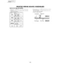
ADJUSTMENT REQUIRED WHEN THE SET IS REPAIRED OR REPLACED
DIGITAL VIDEO Assy
When repaired
No adjustment required.
MR INTERFACE Assy
• Set slide SW according to page 244.
When replaced
SW POWER SUPPLY Module
When replaced
No adjustment required.
• Remove IC1204 (24LC04(1) SN-TBB) from the former
PC Board to replace, and install it to the new PC Board.
Y DRIVE Assy
When repaired
When replaced
1. VOFS/VH/IC5V voltage adjustment
2. Timing adjustment of pulse module
2. Timing adjustment of pulse module
1. SUSB ground timing adjustment
2. Panel white balance adjustment
2. Panel white balance adjustment
1. SUSB ground timing adjustment
2. Panel white balance adjustment
2. Panel white balance adjustment
X DRIVE Assy
When repaired
When replaced
1. VRN voltage adjustment
2. Timing adjustment of pulse module
2. Timing adjustment of pulse module
DIGITAL VIDEO
Assy
Assy
X DRIVE
Assy
Assy
Y DRIVE
Assy
Assy
MR INTERFACE
Assy
Assy
SW POWER SUPPLY
Module
Module
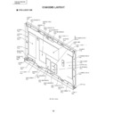
Fig. 1 PC Board Location (rear side view)

