Sharp PZ-50HV2E (serv.man11) Service Manual ▷ View online
44
PZ-50HV2, PZ-50HV2E
PZ-50HV2U
PZ-50HV2U
»
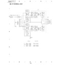
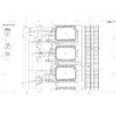
Block Diagram
»
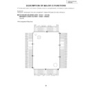
Pin Function
DB
GND
DATA
VDD
GND
VH2
HVO33 - 64
DA
A/B
64 bit Shift Register
64 bit Latch
Selector
Selector
CLR
CLK
LE
OC1
OC2
DATA
GND
VH1
HVO1 - 32
Name
Pin No.
I/O
Num.
Function
CLK
39
I
1
Shift clock (start edge partial response)
DA
44
I/O
1
The serial data input of shifting register
DB
37
I/O
1
The serial data output of shifting register
LE
40
I
1
It output data done a latch of by "L" level
A/B
36
I
1
A shift directional control signal of shift register
CLR
45
I
1
It do data of shift register with "L" by "L" level
OC1
42
I
1
An output control terminal of HVO
OC2
43
I
1
An output control terminal of HVO
HVO
1-30, 51-82, 99, 100
O
64
High voltage drive output (HVO1 - HVO64)
VDD
41
−
1
Logic power supply
GND
34, 35, 38, 46, 47,
87-89, 91-94
87-89, 91-94
−
12
Standard potential. This is common to HVO1 - HVO64.
VH1
84, 85, 49, 50
−
4
The high potential circuit power supply which is common to HVO1 - HVO32
VH2
31, 32, 96, 97
−
4
The high potential circuit power supply which is common to HVO33 - HVO64
NC
33, 48, 95, 83, 86,
90, 98
90, 98
−
7
It is the insulation electrically
45
PZ-50HV2, PZ-50HV2E
PZ-50HV2U
PZ-50HV2U
HD64F2328VF (DIGITAL VIDEO ASSY : IC1101)
• Panel Microcomputer
•
Pin Function
No.
Pin Name
Function
1
CS_23
PE5064 (IC1703) control output
2
NC
NC Terminal
3
VSS
GND
4
VSS
GND
5
VCC
3.3V power supply
6
UA0
Address bus
7
UA1
Address bus
8
UA2
Address bus
9
UA3
Address bus
10
VSS
GND
11
UA4
Address bus
12
UA5
Address bus
13
UA6
Address bus
14
UA7
Address bus
15
UA8
Address bus
16
UA9
Address bus
17
UA10
Address bus
18
UA11
Address bus
19
VSS
GND
20
UA12
Address bus
21
UA13
Address bus
22
UA14
Address bus
23
UA15
Address bus
24
UA16
Address bus
25
UA17
Address bus
26
UA18
Address bus
27
UA19
Address bus
28
VSS
GND
29
UA20
Address bus
30
PA5
NC terminal
31
PA6
NC terminal
32
PA7
NC terminal
33
CE_PN
Enables / for panel microcomputer
34
CE_PN
Enables / for panel microcomputer
35
VSS
GND
36
VSS
GND
37
APLP
The APL value acquisition trigger signal input
38
VD_31
The V signal input from IC1401 (PD6358)
39
VCC
3.3V power supply
40
UD0
Data bus
41
UD1
Data bus
42
UD2
Data bus
43
UD3
Data bus
44
VSS
GND
45
UD4
Data bus
46
UD5
Data bus
47
UD6
Data bus
48
UD7
Data bus
49
UD8
Data bus
50
UD9
Data bus
46
PZ-50HV2, PZ-50HV2E
PZ-50HV2U
PZ-50HV2U
No.
Pin Name
Function
51
UD10
Data bus
52
UD11
Data bus
53
VSS
GND
54
UD12
Data bus
55
UD13
Data bus
56
UD14
Data bus
57
UD15
Data bus
58
VCC
3.3V power supply
59
D_TXD
Communication with IC1207 (module microcomputer)
60
EXT_TXD
Communication with the outside (program notes)
61
D_RXD
Communication with IC1207 (module microcomputer)
62
EXT_RXD
Communication with the outside (program notes)
63
D_CLK
Communication with IC1207 (module microcomputer)
64
P60
NC terminal
65
VSS
GND
66
CS_FLASH
A flash memory control terminal
67
VSS
GND
68
VSS
GND
69
P61
NC terminal
70
UDREQ
IC1703 (PE5064) control terminal
71
P63
NC terminal
72
WE_FLASH
A flash memory note control signal (unused)
73
BUSY
The command receipt of a message lye Norwich output
74
REQ_PU
A communication demand to a module microcomputer
75
SEL23B
IC1703 (PE5064) control terminal
76
CLRB
IC1703 (PE5064) control terminal
77
FR_SEL
The free run select signal output
78
RST31B
The reset output to IC1301, IC1401 (PD6358)
79
RST23B
The reset output to IC1703 (PE5064)
80
FWE
Microcomputer program note control signal
81
RESET
Reset input
82
NMI
The at the rate of tang input (unused)
83
STBY
The hardware standby input (unused)
84
VCC
3.3V power supply
85
XTAL
A clock oscillation child connection terminal
86
EXTAL
A clock oscillation child connection terminal
87
VSS
GND
88
PF7
NC terminal
89
VCC
3.3V power supply
90
PF6
NC terminal
91
RDB
A read control terminal from an outside slave device
92
HWRB
A wright control terminal to an outside slave device
93
PF3
NC terminal
94
PF2
NC terminal
95
PF1
NC terminal
96
PF0
NC terminal
97
P50
NC terminal
98
P51
NC terminal
99
VSS
GND
100
VSS
GND
47
PZ-50HV2, PZ-50HV2E
PZ-50HV2U
PZ-50HV2U
No.
Pin Name
Function
101
P52
NC terminal
102
P53
NC terminal
103
AVCC
3.3V power supply
104
VREF
A/D, D/A reference voltage input (unused)
105
STOPB
The drive control input from IC1703 (PE5064)
106
P41
NC terminal
107
RYBY
The flash memory note ready input
108
ADR_K_EMG_L1
The emergency input from panel bottom address resonance block
109
ADR_K_EMG_U1
The emergency input from panel upper address resonance block
110
ADR_K_EMG_L2
The emergency input from panel bottom address resonance block (unused)
111
ADR_K_EMG_U2
The emergency input from panel upper address resonance block (unused)
112
P47
NC terminal
113
AVSS
GND
114
VSS
GND
115
MUTE_ADR
The panel mute signal input
116
MUTE_SUS
The X and Y drive mute signal output (unused)
117
P15
NC terminal
118
HD
The HD signal input from outside Assy (RGB Assy etc.)
119
P13
NC terminal
120
P12
NC terminal
121
PC_VIDEO
The PC/Video identification output
122
VD
The HD signal input from outside Assy (RGB Assy etc.)
123
MD0
The microcomputer mode of operation select signal input
124
MD1
The microcomputer mode of operation select signal input
125
MD2
The microcomputer mode of operation select signal input
126
PG0
NC terminal
127
CS_31Y
IC1301, IC1401 (PD6358) control signal
128
CS_31X
IC1301, IC1401 (PD6358) control signal

