Sharp PZ-43MR2E (serv.man7) Service Manual ▷ View online
14
PZ-43MR2E
PZ-50MR2E
PZ-50MR2E
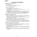
ADJUSTMENT PROCEDURES
Ë
Procedure for turning ON the power
1. Connecting the system
»
Using the system cable, connect the Panel Unit and the AVC System.
»
Connect the Panel Unit to the AC power source.
»
Connect the AVC System to the AC power source.
2. Procedure for turning ON the power
»
Turn ON the AC power switch located on the Panel Unit.
The STANDBY/ON indicator on the Panel Unit will start blinking in red.
(When the AC POWER button on the AVC System is not ON, the STANDBY/ON indicator on the Panel Unit
always blinks in red.)
The STANDBY/ON indicator on the Panel Unit will start blinking in red.
(When the AC POWER button on the AVC System is not ON, the STANDBY/ON indicator on the Panel Unit
always blinks in red.)
»
Turn ON the POWER button located on the AVC System.
The STANDBY/ON indicator on the AVC System will be illuminated in green. Simultaneously, the power indicator
on the Panel Unit will change from blinking in red to illumination in green. Now the system has started up.
The STANDBY/ON indicator on the AVC System will be illuminated in green. Simultaneously, the power indicator
on the Panel Unit will change from blinking in red to illumination in green. Now the system has started up.
»
If the STANDBY/ON indicator on the AVC System is illuminated in red, press the POWER button located on the
remote control unit and the MAIN POWER button located on the Panel Unit. The STANDBY/ON indicators on
the Panel Unit and the AVC System will change from red to green. Now the system has started up.
remote control unit and the MAIN POWER button located on the Panel Unit. The STANDBY/ON indicators on
the Panel Unit and the AVC System will change from red to green. Now the system has started up.
Ë
Procedure for upgrading the software
(1) With the power being OFF, open the top cabinet for the AVC System and then set the slide switch from the
NORMAL position to the WRITE position by inserting a needle-like insulator into the cutout located between
the WHITE port on the rear of the shield case for the PC I/F unit and the RS-232C port.
the WHITE port on the rear of the shield case for the PC I/F unit and the RS-232C port.
(2) Connect the PC having the program installed, to the AVC System using the cross cable for the RS-232C port
(for the details of the program, see Appendix).
(3) Open the MS-DOS window on the PC and then go to the directory in which the software is installed.
(4) Start up the system to which the AVC System and Panel Unit have been connected.
(5) Run “vup.bat (tentaive name)” at the MS-DOS prompt. The software will be upgraded.
(6) Load the file “civc_XXXXa.bhxmain.bhxosd.bhxt (tentaive name)”. It will take approximately a few minutes
(4) Start up the system to which the AVC System and Panel Unit have been connected.
(5) Run “vup.bat (tentaive name)” at the MS-DOS prompt. The software will be upgraded.
(6) Load the file “civc_XXXXa.bhxmain.bhxosd.bhxt (tentaive name)”. It will take approximately a few minutes
until the file has been loaded. Never turn OFF the power or operate the system during this rewriting period.
(7) After the file has been loaded, turn OFF the Panel Unit and the AVC System and then return the slide switch in
the above step 1 from the WRITE position to the NORMAL position. Now the software has been upgraded.
Ë
Procedure for adjusting each part of AVC System
»
The adjustments were made to the best settings at factory. If any setting deviates or if any readjustment is
regarded as necessary when any part is replaced, perform the following steps.
regarded as necessary when any part is replaced, perform the following steps.
»
Any parameter that has been changed within the process adjustment is stored on the memory. If any readjustment
is required, write down the current value before changing it.
is required, write down the current value before changing it.
»
Use a stable AC power source.
»
If the program is upgraded, it will take approximately 1 minute for the EEPROM to be initialized before any video
appears. Therefore, you will need to wait for this time period. Do not turn OFF the power or operate the system
during the period.
appears. Therefore, you will need to wait for this time period. Do not turn OFF the power or operate the system
during the period.
»
If the program is rewritten, write down the parameters that have been changed within the process adjustment
(see “5”.OSD menu and parameters displayed at manual adjustment), initialize the EEPROM, and then reenter
the recorded values.
(see “5”.OSD menu and parameters displayed at manual adjustment), initialize the EEPROM, and then reenter
the recorded values.
15
PZ-43MR2E
PZ-50MR2E
PZ-50MR2E
3. Entering a special mode
1
Entering the process adjustment mode
[Steps]
(1) When using the remote control unit:
Using the system cable, properly connect the Panel Unit and the AVC System, and then turn ON the
power.
After the system has started up, press the PROCESS ADJ button located on the remote control unit.
power.
After the system has started up, press the PROCESS ADJ button located on the remote control unit.
(2) When using buttons on the main unit:
Using the system cable, properly connect the Panel Unit and the AVC System.
Turn ON the power while holding down the INPUT and CH UP buttons located the Panel Unit.
Turn ON the power while holding down the INPUT and CH UP buttons located the Panel Unit.
[Description]
Various adjustments can be made manually.
2
Entering the inspection process mode
[Steps]
After the system has started up, press the PROCESS ADJ button located on the remote control unit.
Set the parameter SIGNAL INFO to 1 on page 6 or 7 of the PROCESS ADJUSTMENT A MODE MENU.
Subsequently, make the necessary adjustments in accordance with the above menu.
Set the parameter SIGNAL INFO to 1 on page 6 or 7 of the PROCESS ADJUSTMENT A MODE MENU.
Subsequently, make the necessary adjustments in accordance with the above menu.
3
Procedure for setting up delivery
[Steps]
After the system has started up, press the DELIVERY SETUP button located on the remote control unit.
(Within the adjustment process, the channel settings remain unchanged. Once you exit the process adjustment
mode, the channel settings entered in the delivery adjustment mode become valid.)
(Within the adjustment process, the channel settings remain unchanged. Once you exit the process adjustment
mode, the channel settings entered in the delivery adjustment mode become valid.)
[Description]
The user’s adjustment parameters and others will be set to the default values. The channel settings will also
be initialized.
be initialized.
4. Exiting a special mode
(1) Process adjustment mode: Press the PROCESS ADJ button located on the remote control unit or turn OFF the
power.
(2) Inspection process mode: Set the parameter SIGNAL INFO to 0 on page 6 or 7 of the PROCESS ADJ A MODE
MENU or turn OFF the power.
(3) Delivery setup: After the delivery setup has been finished, the process adjustment mode is automatically
selected. To exit the process adjustment mode, press the PROCESS ADJ button located on the remote control
unit or turn OFF the power.
unit or turn OFF the power.
5. OSD menu and parameters displayed at manual adjustment
*
The default values may slightly differ depending upon the program version to be rewritten.
*
The settings are not initialized to the default values by merely rewriting the program. (See the paragraph for
Preparation for adjustment.)
Preparation for adjustment.)
(1) Descriptions of special buttons in process adjustment mode
Cursor UP key
: Proceeds to the previous page.
Cursor DOWN key : Returns to the next page.
VOL UP key
VOL UP key
: Increases the adjusted value by 1.
VOL DOWN key
: Decreases the adjusted value by 1.
Cursor LEFT key : Decreases the adjusted value by 10.
Cursor RIGHT key : Increases the adjusted value by 10.
CH UP key
Cursor RIGHT key : Increases the adjusted value by 10.
CH UP key
: Moves up the cursor.
CH DOWN key
: Moves down the cursor.
16
PZ-43MR2E
PZ-50MR2E
PZ-50MR2E
Ë
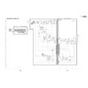
Organization of process adjustment screen
Parameter display
Ë
+B Adj3.3V
Ë
+B Adj2.5V
Ë
PAL Y CONTRAST
Ë
PAL COLOR GAIN
Ë
MAIN CR GAIN PAL
Ë
MAIN SUBBRIGHT 15K
Ë
MAIN CONTRAST 15K
Ë
SUB PAL Y
Ë
SUB PAL COLOR GAIN
Ë
PEAK ACL SW
Ë
SECAM Y CONTRAST
Ë
SECAM COLOR GAIN
Ë
MAIN CR GAIN SECAM
Ë
N358 Y CONTRAST
Ë
N358 COLOR GAIN
Ë
MAIN CR GAIN N358
Ë
N358 TINT
Ë
COMP 15K Y CONTRAST
Ë
COMP 15K COLOR GAIN
Ë
MAIN CR GAIN COMP15K
Ë
COMP HDTV SUB BRIGHT
Ë
COMP HDTV CONTRAST
Ë
DATA COPY
Setting range
0 ~ 255
0 ~ 255
0 ~
0 ~ 255
0 ~
63
0 ~
63
0 ~ 255
0 ~
0 ~
63
0 ~
15
-30 ~
30
0 ~
63
OFF/ON
0 ~
63
0 ~
63
0 ~ 255
0 ~
0 ~
63
0 ~
63
0 ~ 255
-30 ~
30
0 ~
63
0 ~
68
0 ~ 255
0 ~
0 ~
63
0 ~
15
OFF/ON
Description
3.3 V adjustment
2.2 V adjustment
PAL Y level adjustment
PAL colour density adjustment
PAL Cr level adjustment
Pedestal level adjustment (15 k)
PCB input amplitude adjustment (15 k)
Sub PAL Y level adjustment
Sub PAL colour density adjustment
2.2 V adjustment
PAL Y level adjustment
PAL colour density adjustment
PAL Cr level adjustment
Pedestal level adjustment (15 k)
PCB input amplitude adjustment (15 k)
Sub PAL Y level adjustment
Sub PAL colour density adjustment
SECAM Y level adjustment
SECAM colour density level adjustment
SECAM Cr level adjustment
N358 Y level adjustment
N358 colour density adjustment
N358 Cr level adjustment
N358 tone adjustment
COMP 15 k Y level adjustment
COMP 15 k colour density adjustment
COMP 15 k Cr level adjustment
COMP HDTV black level adjustment
COMP HDTV Y level adjustment
COMP HDTV colour density adjustment
The values for the above parameters should be written down before the EEPROM is replaced on
the AVC system.
Note: The contents on the adjustment process menu may be somewhat different depending on
the AVC system.
Note: The contents on the adjustment process menu may be somewhat different depending on
the program's version-up.
Maker Select
Ë
+Badj3.3V
Ë
+Badj2.5V
KEY WRITE
Ë
DATA COPY
INDUSTRY INIT
CENTER Version
OSD Version
CVIC Version
TTXP Version
MONITOR Version
PANEL Version
FLASH Version
MONITOR Model
Model Select MONITOR
STANDBY TYPE
SHARP
127
024
OFF
OFF
OFF
MR MAIN E 2001/11/28K
MR OSD 2001/09/10 A
W2001/10/02 17:28 X2001/10/02 V2001/09/12 09:12
TTX PRG
068
F6 91 xx
-00
-05
01
1
0
Page
Input Source
HDCP
INPUT1 No SIG
1/16
HDCP:ON EUROPE
EUROPE
Destination for MAIN unit
Destination for AV unit
Distinguish Signal
17
PZ-43MR2E
PZ-50MR2E
PZ-50MR2E
6. Procedures before and after replacing the PC I/F unit
1) Before replacing the PC I/F unit, write down the values for the parameters listed on the 2nd and 3rd pages of
the Adjustment Process A screen.
If the values for the parameters cannot be written down because the PC I/F unit is completely broken or for any
other reason, make all the adjustments in accordance with the paragraph for Adjustment procedure and
parameters, rather than the following procedures. (End)
Set the parameters listed on the 2nd and 3rd pages of the Adjustment Process A screen to the values you have
written down.
7. Adjustment parameters
1) Analog adjustment
(1) Prior adjustment for AVC system chassis
(2) PAL signal adjustment
1
Destination check
1. Call the process adjustment mode.
2. Check that the destination is “Europe”.
2. Check that the destination is “Europe”.
Adjustment item
Description
Adjustment procedure
2
AVC center 3.3V
adjustment
adjustment
Connect DC voltmeter to
TP1702.
TP1702.
Adjust output voltage of DC/DC 5 V line to
3.3 V.
Adjusted value: 3.25~3.29 V
3.3 V.
Adjusted value: 3.25~3.29 V
3
AVC center 2.5V
adjustment
adjustment
Connect DC voltmeter to
TP1701.
TP1701.
Adjust output voltage of DC/DC 2.5 V line to
2.6 V.
Adjusted value: 2.60~2.64 V
2.6 V.
Adjusted value: 2.60~2.64 V
1
Setup
1. Set colour system to “PAL”.
2. Select PAL source.
2. Select PAL source.
100% colour bar signal including 100% white, such
as split field colour bar
as split field colour bar
Adjustment item
Description
Adjustment procedure
2
Tuner Y level
adjustment
adjustment
1. Adjust TP1101 so that the Y signal without the
chroma component should be 1.00 ±0.05 Vp-p
(between the bottom of sync signal and the white
peak).
(between the bottom of sync signal and the white
peak).
3
PAL Y CONTRAST
adjustment
adjustment
1. Adjust TB1274_MAIN output (TP803) to
0.7 ±0.05 Vp-p.
4
PAL COLOR GAIN
adjustment
adjustment
1. Adjust TB1274_MAIN
output (TP802) to
0.35 ±0.025 Vp-p.
0.35 ±0.025 Vp-p.
5
MAIN CR GAIN PAL
adjustment
adjustment
1. Adjust TB1274_MAIN output
(TP801) to 0.35 ±0.05 Vp-p.
6
MAIN CONTRAST
adjustment
adjustment
Turn off the PEAK ACL control. Adjust the output
(TP815) of IC810 to have 1.1 ±0.05 Vp-p from the
pedestal level.
(TP815) of IC810 to have 1.1 ±0.05 Vp-p from the
pedestal level.
Press the DUAL screen button.
Select the special DUAL screen settings for adjustment
(so that the same video source is reflected on MAIN/
SUB).
(so that the same video source is reflected on MAIN/
SUB).
7
SUB PAL Y adjustment
1. Adjust TB1274_SUB output (TP806) to
0.9 ±0.05 Vp-p.
8
SUB PAL COLOR
GAIN adjustment
GAIN adjustment
1. Adjust TB1274_SUB output (TP805) to
0.9 ±0.05 Vp-p.
0.35V
0.35V
Display

