Sharp LC-M3700 (serv.man6) Service Manual ▷ View online
13
LC-M3700
LC-M3710
LC-M3710
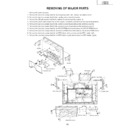
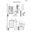
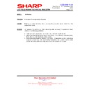
REMOVING OF MAJOR PARTS
1. Remove the terminal cover.
2. Remove the four lock screws that fix the temporary stand and remove the simple stand.
3. Remove the two lock screws that fix the handle and remove the handle.
4. Remove the 29 lock screws that fix the cabinet B and remove the cabinet B.
5. Remove the seven lock screws that fix the cabinet B (bottom) and remove the cabinet B (bottom).
6. Remove the two lock screws that fix the terminal cover B and remove the terminal cover B.
7. Remove the two lock screws that fix the terminal cover A and remove the terminal cover A.
8. Remove the four lock screws that fix the PC I/F PWB shield and remove the PC I/F PWB shield.
9. Remove the four lock screws that fix the monitor PWB shield and remove the monitor PWB shield.
10. Remove the four lock screws that fix the FPC holder (left) and remove the FPC holder (left).
11. Remove the four lock screws that fix the FPC holder (right) and remove the FPC holder (right).
3
4
4
3
1
2
Temporary stand
Handle
Handle
Terminal cover
SC4101
SC4102
8
10
11
6
7
5
5
9
FPC holder (left)
PC I/F PWB shield
Wire Holder
Monitor PWB shield
FPC holder (right)
Terminal cover B
Terminal cover A
Cabinet B (bottom)
14
LC-M3700
LC-M3710
LC-M3710
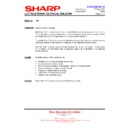
12. Disconnect the connectors from each PWB.
13. Remove the two lock screws that fix the key PWB and remove the key PWB.
14. Remove the two lock screws that fix the R/C LED PWB and remove the R/C LED PWB.
15. Remove the two lock screws that fix the speaker-L PWB and remove the speaker-L PWB.
16. Remove the two lock screws that fix the AC inlet PWB and remove the AC inlet PWB.
17. Remove the two lock screws that fix the terminal-1 PWB and remove the terminal-1 PWB.
18. Remove the two lock screws that fix the terminal-2 PWB and remove the terminal-2 PWB.
19. Remove the two lock screws that fix the speaker-R PWB and remove the speaker-R PWB.
20. Remove four lock screws that fix the speaker angle and remove the speaker angle.
P7615
P7616
P7618
P7644
P7643
P7647
P7642
P7641
P7614
P7613
P7612
P7611
P7649
P202
SC2406
SC1506
P1505
P1507
P1504
SC2405
P2508
P2302
P2301
P1801
P1501
CN1
CN9
CN8
CN11
SC1103
P1101
CN4701
CN3701
CN2701
CN2702
CN3702
P7803
P7802
P7557
P202
P7554
P7507
P101
P7505
P7506
P7501
P7502
P7503
P7504
P7552
P7551
P7553
CN1703
CN1704
CN1702
CN1705
CN1701
CN1706
CN1707
P7704
P7707
P2004
P2003
P7705
P2005
CN2001
SC4601
SC4602 SC4604
SC4603
P151
12
12
12
12
12
12
12
12
12
12
20
19
18
13
14
15
16
17
Speaker angle
Speaker-R PWB
Key PWB
R/C LED PWB
Terminal-1 PWB
Terminal-2 PWB
Speaker-LPWB
AC inlet PWB
15
LC-M3700
LC-M3710
LC-M3710
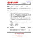
21. Remove the inverter-3 PWB.
22. Remove the three lock screws that fix the inverter-4 PWB and remove the inverter-4 PWB.
23. Remove the four lock screws that fix the main PWB and remove the main PWB.
24. Remove the four lock screws that fix the monitor PWB and remove the monitor PWB and monitor PWB angle.
25. Remove the two lock screws that fix the PC I/F PWB and remove the PC I/F PWB.
26. Remove the four lock screws that fix the DC/DC PWB and remove the DC/DC PWB.
27. Remove the one lock screw that fixes the holder B assembly and remove the holder B assembly.
28. Remove the one lock screw that fixes the holder A assembly and remove the holder A assembly.
29. Remove the inverter-1 PWB.
30. Remove the one lock screw that fixes the inverter 2 PWB and remove the inverter-2 PWB.
28
27
26
25
24
21
22
23
31
30
29
Holder A assembly
Holder B assembly
DC/DC PWB
PC I/F PWB
Monitor PWB
Inverter-3 PWB
Inverter-4 PWB
Inverter-1 PWB
Inverter-2 PWB
Main PWB
Power PWB
Monitor PWB angle
PC I/F PWB
angle
angle
16
LC-M3700
LC-M3710
LC-M3710
»
Cautions in handling the liquid crystal panel
1. Handle the liquid crystal panel in a clean room (Humidity: 50% or more).
1. Handle the liquid crystal panel in a clean room (Humidity: 50% or more).
32. Remove the five lock screws that fix the liquid crystal panel and remove the liquid crystal panel unit.
33. Remove the three lock screws that fix each sheet-fixing angle and remove each sheet-fixing angle.
34. Remove the reflection/shade sheet, prism sheet, diffusion sheet and diffusion plate.
35. Remove the three lock screws that fix each lamp holder (upper, lower) and remove each lamp holder (upper,
lower).
36. Remove the lamp assembly from the lamp clip.
32
33
34
33
35
35
36
Sheet-fixing angle
Sheet-fixing angle
Reflection/shade sheet
Prism sheet
Lamp holder (upper)
Lamp holder (lower)
Lamp holder (upper)
Lamp holder (lower)
Back shield
Lamp unit
Diffusion plate
Diffusion plate
Display

