Sharp LC-80LE646E (serv.man7) Service Manual ▷ View online
LC-60/70LE740E/RU,741E/S,743E,60LE840E/RU,841E/S,843E,80LE645E/RU,646E/S,648E
6 – 61
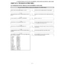
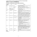
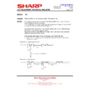
Table 1. Concrete flashing pattern
*2: It depends on the system. The power supply error suitable for the product is defined.
*3: For details, refer to ERROR STANDBY CAUSE on the adjustment process screen.
*4: If the boot section is abnormal, there is no flashing (flashing disabled).
MONITOR ERR STBY table
Item
Expression for a rough content
Expression for Details
Cause
low-speed
blinking
high-speed
blinking
low-speed
blinking
high-speed
blinking
Lamp system failure Flashes once
—
Flashes once
Flashes once
Lamp error
Power PWB failure
Flashes twice
—
Flashes twice
Flashes once
Power Error 1 AC_DET error (*2)
(Power failure, etc.)
Flashes twice
Power Error 2 UR+13.5V error (*2)
Flashes 3 times
Power Error 3 D3.3V error (*2)
Flashes 5 times
Panel power supply error
Main PWB failure
Flashes 3 times
—
Flashes 3 times
Flashes once
Initial communication error
(Communication Flashes
twice
Start-up confirmation communication error
failure, etc.)
Flashes 3 times
Regular communication error
Flashes 5 times
Other communication error
Others
Flashes 4 times
—
Flashes 4 times
Flashes once
Temperature error
Flashes twice
Sync error
Flashes 3 times
Notification from the main microprocessor
(*3)
(*3)
Upgrade executing
smoothness
changes.
—
—
—
Version upgrading
Upgrade completion
a staircase
pattern.
—
—
—
Version upgrade succeeded
Upgrade failed
—
Flashing
(Continuous)
—
—
Version upgrade failed
ROM data failure
—
Flashing
(Continuous)
—
—
Start-up after failing version upgrade (*4)
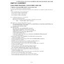
Outline: Communication/Power failure detected by the monitor microprocessor (IC2001) is stored on EEPROM, states can be confirmed in the
adjustment process mode.
Location: Page (1/20) of the adjustment process mode: MONITOR ERR CAUSE “0” if there is no error. It is cleared to 0 on the page (2/20) of the
adjustment process mode.
Display Error
description
02
Start-up communication error 2
Initial communication from the main CPU is not received.
03
Start-up communication error 3
Only the initial communication is received.
04
Start-up communication error 4
Until panel information request reception
05
Start-up communication error 5
Until initialization completion reception
06
Start-up communication error 6
Until version notification transmission
07
Start-up communication error 7
Until start-up information notification transmission
08
Start-up communication error 8
Until start-up information response reception
09
Start-up communication error 9
Until time-out setting reception
0A
Communication error A
REQ time-out
0B
Communication error B
Restart time-out during the beginning of time acquisition start-up
0C
Communication error C
Ending sequence time-out
0D
Communication error D
Preset start-up time-out during completion
0E
Communication error E
Download start-up time-out
0F
Communication error F
Time acquisition time-out
11
Communication error H
Regular communication time-out
16
Panel-related error
Lamp failure
1A
Other error 2
Monitor temperature failure
1D
Power supply error 1
PS_ON (AC_DET) failure
1E
Power supply error 2
D_POW (DET_13V) failure
1F
Power supply error 3
D_POW (DET_D3V3) failure
21
Power supply error 5
Panel power failure
23
Other error 3
Error standby request from the main CPU
LC-60/70LE740E/RU,741E/S,743E,60LE840E/RU,841E/S,843E,80LE645E/RU,646E/S,648E
6 – 62
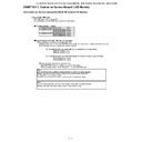
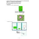
LED flashing timing chart at the time of the error
1) Low-speed blinking
2) Lamp failure details (Low-speed blinking: Flashes once + High-speed blinking)
3) Power failure details (Low-speed blinking: Flashes twice + High-speed blinking)
Error type
Expression of Central Icon LED
Lamp failure
low-speed blinking
Flashes once
low-speed blinking
Flashes once
H: ON
L: OFF
Refer to “Lamp failure details”.
LOW/High blinking by pressing the [MENU] key on the remote
control.
LOW/High blinking by pressing the [MENU] key on the remote
control.
Power failure
low-speed blinking
Flashes twice
low-speed blinking
Flashes twice
H: ON
L: OFF
Refer to “Power failure details”.
LOW/High blinking by pressing the [MENU] key on the remote
control.
LOW/High blinking by pressing the [MENU] key on the remote
control.
Communication
failure with main CPU
low-speed blinking
Flashes 3 times
failure with main CPU
low-speed blinking
Flashes 3 times
H: ON
L: OFF
Refer to “Communication failure details”.
LOW/High blinking by pressing the [MENU] key on the remote
control.
Communication line failure or main CPU communication failure.
LOW/High blinking by pressing the [MENU] key on the remote
control.
Communication line failure or main CPU communication failure.
Others
low-speed blinking
Flashes 4 times
low-speed blinking
Flashes 4 times
H: ON
L: OFF
Refer to “Other failure details”.
LOW/High blinking by pressing the [MENU] key on the remote
control.
LOW/High blinking by pressing the [MENU] key on the remote
control.
Error type
Expression of Central Icon LED
Note: Pins are monitor microprocessor pins unless otherwise
specified (IC2001).
specified (IC2001).
Lamp failure
Flashes once
(High speed)
(High speed)
H: ON
L: OFF
LAMP_ERR (19pin): Abnormal H.
Confirmed after 8 consecutive detections at 64ms intervals
(detected only when the backlight is on).
Confirmed after 8 consecutive detections at 64ms intervals
(detected only when the backlight is on).
NOTE: After 5 detection counts, the lamp cannot be activated
except in the monitoring process.
To confirm the problem, “Lamp Error detection off-mode”
is prepared.
This mode compulsorily starts the set disregarding the
count.
Please refer to [7. Lamp Error detection (ADJUSTMENT
PROCEDURE)]
To confirm the problem, “Lamp Error detection off-mode”
is prepared.
This mode compulsorily starts the set disregarding the
count.
Please refer to [7. Lamp Error detection (ADJUSTMENT
PROCEDURE)]
Error type
Expression of Central Icon LED
Note: Pins are monitor microprocessor pins unless otherwise
specified (IC2001).
specified (IC2001).
PS_ON
AC_DET failure
Flashes once
(High speed)
AC_DET failure
Flashes once
(High speed)
H: ON
L: OFF
AC_DET (28pin): Abnormal (L).
If error is detected during start-up or operation, the power is turned
on again by interrupt handling (instantaneous blackout process-
ing).
If error is detected during start-up or operation, the power is turned
on again by interrupt handling (instantaneous blackout process-
ing).
SM_POW
Main 13V failure
Flashes twice
(High speed)
Main 13V failure
Flashes twice
(High speed)
H: ON
L: OFF
DET_13V (32pin): Abnormal (L). Main 13V is not applied.
If error is detected during start-up or operation, the power is turned
on again by polling.
If error is detected during start-up or operation, the power is turned
on again by polling.
D_POW
Digital 3.3V failure
Flashes 3 times
(High speed)
Digital 3.3V failure
Flashes 3 times
(High speed)
H: ON
L: OFF
DET_D3V3 (33pin): abnormal (L). Digital 3.3V is not applied.
If error is detected during start-up or operation, the power is turned
on again by polling.
on again by polling.
PANEL_POW
Panel 12V failure
Flashes 5 times
(High speed)
Panel 12V failure
Flashes 5 times
(High speed)
H: ON
L: OFF
DET_PNL12V (34pin): abnormal (L). DET_PNL12V is not applied.
Detection starts after receiving command from Panel Power ON.
The power is turned off by polling.
The power is turned off by polling.
100ms
400ms
1.6sec
LC-60/70LE740E/RU,741E/S,743E,60LE840E/RU,841E/S,843E,80LE645E/RU,646E/S,648E
6 – 63
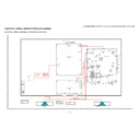
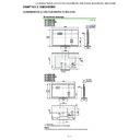
4) Communication failure details (Low-speed blinking: Flashes 3 times + High-speed blinking)
5) Other failure details (Low-speed blinking: Flashes 4 times + High-speed blinking)
Error type
Expression of Central Icon LED
Note: Basically, debug print logs are analyzed or
communication logs are analyzed by a bus monitor.
communication logs are analyzed by a bus monitor.
Initial communication
reception failure
Flashes once
(High speed)
reception failure
Flashes once
(High speed)
H: ON
L: OFF
Initial communication from the main CPU is not received.
(Request for the monitor model No. is not received.)
→ Communication line failure or main CPU start-up failure.
(Request for the monitor model No. is not received.)
→ Communication line failure or main CPU start-up failure.
Start-up confirmation
reception failure
Flashes twice
(High speed)
reception failure
Flashes twice
(High speed)
H: ON
L: OFF
Start-up reason confirmation from the main CPU cannot be
received.
(Startup communication until start-up reason notification command
is not received.)
→ Main CPU start-up failure or monitor microprocessor reception
failure.
received.
(Startup communication until start-up reason notification command
is not received.)
→ Main CPU start-up failure or monitor microprocessor reception
failure.
Regular communica-
tion failure
tion failure
Flashes 3 times
(High speed)
(High speed)
H: ON
L: OFF
Regular communication that is performed at 1 second intervals in
the normal operation is interrupted.
→ Main CPU operation failure or monitor microprocessor
reception failure.
the normal operation is interrupted.
→ Main CPU operation failure or monitor microprocessor
reception failure.
Other communica-
tion failure
tion failure
Flashes 5 times
(High speed)
(High speed)
H: ON
L: OFF
When a request (PM_REQ=H) is sent from the main microproces-
sor, the request command is not output from the main CPU, etc.
→ Main CPU operation failure or monitor microprocessor
reception failure.
sor, the request command is not output from the main CPU, etc.
→ Main CPU operation failure or monitor microprocessor
reception failure.
Error type
Expression of Central Icon LED
Monitor temperature
failure
failure
Flashes once
(High speed)
(High speed)
H: ON
L: OFF
If the panel temperature is 60
°C or more for 15s or more in a row,
CAUTION appears on the OSD (flashes in red in the lower right
screen).
If the panel temperature is 60
screen).
If the panel temperature is 60
°C or more for 25s or more in a row,
error standby is activated.
(MONITOR MAX TEMP on page (12/20) of the adjustment pro-
cess: Change AD value for temperature failure): Thermistor
(MONITOR MAX TEMP on page (12/20) of the adjustment pro-
cess: Change AD value for temperature failure): Thermistor
Main failure
Flashes 3 times
(High speed)
(High speed)
H: ON
L: OFF
Main microprocessor detection error (CPU temperature error, etc.)
Details are displayed on page (1/20) of the adjustment process for
the main microprocessor.
Details are displayed on page (1/20) of the adjustment process for
the main microprocessor.

