Sharp LC-52XS1E (serv.man4) Service Manual ▷ View online
LC-52XS1E/RU/LC-65XS1E/RU
4 – 1
LC-52XS1E
Service Manual
CHAPTER 4.
TROUBLESHOOTING TABLE
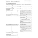
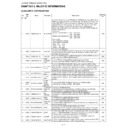
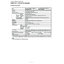
[1] Power supply Troubleshooting
No power supplied (Front LED does not turn on). Power switched on but no power supplied. (Front LED does not turn Red
→ Green)
YES
Are the power cord connector correctly connected to the body?
NO
Reconnect the power cord correctly and switch on the power
again.
again.
YES
Is connector AC/AC2 of the AC Inlet unit (RUNTKA485WJQZ: 52/
RUNTKA491WJQZ: 65) connected normally?
RUNTKA491WJQZ: 65) connected normally?
NO
Reconnect the AC Inlet unit correctly and switch on the power
again.
again.
[MAIN-POWER UNIT]
RDENCA304WJQZ
RDENCA304WJQZ
YES
Is a main fuse (F7601, F7602) normal?
NO
When the fuse cuts even if the main fuses are exchanged and the
power supply is turned on again.
Check (C7901, DS7901, C7901, IC7901) of the BU5V primary
side in the MAIN power unit
power supply is turned on again.
Check (C7901, DS7901, C7901, IC7901) of the BU5V primary
side in the MAIN power unit
YES
Please check the PS_ON signal line of IC7002 (SUB-MICON) 67
pin on IF board.
pin on IF board.
NO
Please check whether BU5V is normally outputted to pin 6 and 7
of PD connector (CN7101)?
of PD connector (CN7101)?
NO
Please check whether there is parts which are out of order on
BU5V lines, or a shorting circuit.
BU5V lines, or a shorting circuit.
YES
YES
Please check whether about parts out of order on the BU5V line
or the short-circuited circuits.
or the short-circuited circuits.
YES
NO
Please check the power circuit of a BU5V line system.
T7901, D7101, PC7901, PC7902, C7102, IC7101,
D7904, IC7901
T7901, D7101, PC7901, PC7902, C7102, IC7101,
D7904, IC7901
Please remove the part that breaks down or is short-circuited,
and, check it again.
and, check it again.
Please check whether exchange fuses and a power supply is
turned on again.
turned on again.
NO
Please check whether UR15V is normally output to pin 1 and 2 of
PE connector (CN7001).
PE connector (CN7001).
NO
Is the fuse (F7802, F7803) normal?
YES
YES
Please check whether about parts out of order on the UR15V line
or the short-circuited circuits.
or the short-circuited circuits.
YES
NO
Please check the power circuit of a UR15V line system.
T7801, D7001, PC7801, PC7802, C7002, IC7001,
Q7810, Q7812, IC7803
T7801, D7001, PC7801, PC7802, C7002, IC7001,
Q7810, Q7812, IC7803
Please remove the part that breaks down or is short-circuited,
and, check it again.
and, check it again.
A MAIN-power supply unit is normal. When still amusing, please
improve connection of harness and a B/B connector.
improve connection of harness and a B/B connector.
YES
LED-PANEL-power source
[SUB1/2/3-POWER UNIT]
Check each voltage about RDENCA305/6/7WJQZ described in
the next page and survey an abnormal location.
[SUB1/2/3-POWER UNIT]
Check each voltage about RDENCA305/6/7WJQZ described in
the next page and survey an abnormal location.
LC-52XS1E/RU/LC-65XS1E/RU
4 – 2
[2] The voltage check of each substrate unit
2-1 IF board voltage check
2-2 MAIN-POWER-UNIT voltage check (RDENCA304WJQZ)
2-3 SUB-POWER-UNIT1 voltage check (RDENCA305WJQZ)
2-4 SUB-POWER-UNIT2 voltage check (RDENCA306WJQZ)
2-5 SUB-POWER-UNIT3 voltage check (RDENCA307WJQZ)
2-6 LCD_CONTROL_UNIT voltage check
2-7 LED_CONTROL_UNIT voltage check
Harness-NO
REF-NO
Pin-NO
Voltage
Description
PD
P5801
6/7
5
BU5V
PE
P5802
1/2
15
UR15V
6/7
15
S15V
US
P7901
1
5
D5V
DC
P7903
1
5
DC5V
KM
P7905
1
3.3
BU3.3V
ADJ
P7906
1
3.3
BU3.3V
RA
P7907
1
3.3
BU3.3V
2
3.3
OPC3.3V
Harness-NO
REF-NO
Pin-NO
Voltage
Description
PD
CN7101
6/7
5
BU5V
PE
CN7001
1/2
15
UR15V
5/6
15
S15V
PI
CN7104
1
5
UR15V
PS3
CN7103
1
5
BU5V
PS1
CN7102
1/2
5
BU5V
6/9
27
27V
7/10
20
20V
ACM
CN7602
1/2
220
220VAC
Harness-NO
REF-NO
Pin-NO
Voltage
Description
P1
CN7104
1
15
UR15V
PS1
CN7102
1/2
5
BU5V
6/9
27
27V
7/10
20
20V
PS3
CN7103
1
5
BU5V
AC1
CN5602
1/2
220
220VAC
Harness-NO
REF-NO
Pin-NO
Voltage
Description
PS2
CN5004
1
5
BU5V
4
27
27V
5
20
20V
LA2
CN5001
1/2
27
27V
5/6
20
20V
AC2
CN5602
1/2
220
220VAC
Harness-NO
REF-NO
Pin-NO
Voltage
Description
P1
CN7104
1
15
UR15V
PS1
CN7102
1/2
5
BU5V
6/9
27
27V
7/10
20
20V
PS3
CN7103
1
5
BU5V
AC3
CN5601
1/2
220
220VAC
Harness-NO
REF-NO
Pin-NO
Voltage
Description
LC
P4802
9/10
12
12V
Harness-NO
REF-NO
Pin-NO
Voltage
Description
P1
CN10
1
15
UR15V
LE
CN12
1
3.3
BU3.3V
LC-52XS1E/RU/LC-65XS1E/RU
4 – 3
2-8 LED_DISTRIBUTION2_UNIT voltage check
2-9 IF board regulator output voltage check
2-10 IF board frequency check
Harness-NO
REF-NO
Pin-NO
Voltage
Description
LA3
CN3
1/2/3
27
27V
7/8
20
20V
LA1
CN1
1/2/3
27
27V
5/6
20
20V
LA2
CN2
1/2/3
27
27V
5/6
20
20V
Ref No
Part-code
Output-
Voltage [V]
Description
IC6005
VHiPQ1LA185-1Y
1.8
for HDMI SW
IC6101
VHiR1173S18-1Y
1.8
for HDMI Rx
IC6051
VHiBH33FB1G-1Y
3.3
for LVDS Tx
IC6352
VHiPQ1LA185-1Y
1.8
for IrSS
IC6603
VHiPQ1X251M-1Y
2.5
for Seine2D
IC6604
VHiR1173S33-1Y
3.3
for Seine2D
IC6606
VHiBD00K5WP-1Y 1.2
for
Seine2D
IC6802
VHiR1173S18-1Y
1.8
for A-DSP
IC6803
VHiPQ1LA335-1Y
3.3
for A-DSP
IC6901
VHiPQ1X331M-1Y
3.3
for 1BitAMP
IC7102
VHiR1173S25-1Y
2.5
for FPGA
IC7104
VHiR1173S12-1Y 1.2
for
FPGA
IC7501
VHiBH33FB1G-1Y
3.3
for LVDS Tx2
IC5803
VHiBA33BCFP-1Y
3.3
for Backup
TL5903
—
3.3
3.3V
TL5904
—
5
5V
TL5905
—
1.3
1.3V
TL5906
—
1.8
1.8V
Ref No
Pin-No
Frequency
Description
IC6102
5
148.5MHz
HDMI_RX At the time of a 1080p
60Hz input
60Hz input
94/95
28.322MHz
X6101
X6301
3
33.3MHz
IC6301
1/16
27MHz
CLK_GEN X6303
7
54MHz
9
74.25MHz
At the time of a 1080p 60Hz
input
input
12
48MHz
IC6302
1/16
27MHz
CLK_GEN X6303
7
54MHz
8
33MHz
9
33MHz
12
33MHz
X6304
3
48MHz
IC6351
J8/J9
48MHz
X6351 IRSS
IC6702
H5
33MHz
CPLD
IC6804
21/22
12.288MHz
S-DSP
IC6902
17/18
24.576MHz
1bit-AMP
IC7502
15
148.5MHz
LVDS_Tx At the time of a 1080p
60Hz input
60Hz input
IC7002
8/9
32KHz
MICON X7001
11/13
20MHz
FL7001
LC-52XS1E/RU/LC-65XS1E/RU
4 – 4
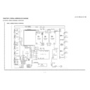
[3] Backlight POWER Check (details)
1. SUB-POWER-UNIT (1/2/3) (Backlight POWER) power supply input
• • • AC1, AC2, AC3terminal • • • He is 220VAC.
2. SUB-POWER-UNIT (Backlight POWER) Power supply output
• • • LA1/2/3terminal, PS1/2/3 terminal is as follows.
SUB-POWER-UNIT (1/2/3)
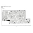
3. The input-and-output power supply of POWER-DISTRIBUTION-UNIT
• • • The voltage of LA1/2/3, CN4, CN1-CN8 terminal is as follows.
POWER-DISTRIBUTION-UNIT
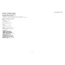
BACK LIGHT POWER FAILURE
1pin
2pin
3pin
4pin
5pin
6pin
7pin
8pin
9pin
10pin
LA1/LA2
27V
27V
G
G
20V
20V
G
G
G
—
52/65
LA3
27V
27V
27V
G
G
G
20V
20V
G
G
65
1pin
2pin
3pin
4pin
5pin
6pin
7pin
8pin
9pin
10pin
11pin
PS1
BU5V
BU5V
LED_ON
OVP
G
27V
20V
G
27V
20V
G
52/65
PS2
BU5V
LED_ON
OVP
27V
20V
G
—
—
—
—
—
52/65
PS3
BU5V
LED_ON
OVP
27V
20V
G
—
—
—
—
—
65
1pin
2pin
3pin
4pin
5pin
6pin
7pin
8pin
LA1/LA2
CN1/2
27V
27V
G
G
20V
20V
G
G
52/65
LA3
CN3
27V
27V
27V
G
G
G
20V
20V
65
1pin
2pin
3pin
4pin
5pin
6pin
7pin
8pin
9pin
10pin
11pin
12pin
13pin
14pin
CN4
20V_
R
20V_
R
20V_
R
20V_
R
20V_
R
G
G
27V_G
B
27V_G
B
27V_G
B
27V_G
B
27V_G
B
27V_G
B
27V_G
B
52/65
15pin
16pin
17pin
18pin
19pin
20pin
21pin
22pin
23pin
G
G
G
G
G
G
G
G
G
52/65
1pin
2pin
3pin
4pin
5pin
6pin
CN1
20V_R
G
G
G
27V_G
27V_B
POWER-DISTRIBUTION-UNIT1
52/65
CN2
20V_R
G
G
G
27V_G
27V_B
POWER-DISTRIBUTION-UNIT1
52/65
CN3
20V_R
G
G
G
27V_G
27V_B
POWER-DISTRIBUTION-UNIT1
52/65
CN5
20V_R
G
G
G
27V_G
27V_B
52/65
• • •
20V_R
G
G
G
27V_G
27V_B
• • •
CN7
20V_R
G
G
G
27V_G
27V_B
52/65
CN8
20V_R
G
G
G
27V_G
27V_B
65

