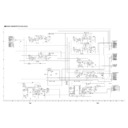
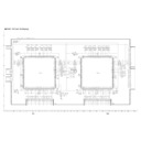
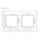
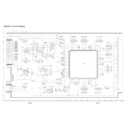
Sharp LC-45GD1E (serv.man29) Service Manual ▷ View online
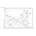
49
TU-45GD1E
LC-45GD1E
LC-45GD1E
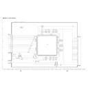
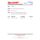
TROUBLE SHOOTING TABLE
(Continued)
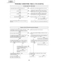
No sound (1) (Output from external input terminals)
Connect an external unit to CENTRE CHANNEL
INPUT
. Does the audio
come out of Display-Speaker?
Is there the audio signal input at the CENTRE CHANNEL
INPUT
terminal (J1
105)?
Are the inputs at pins (1) and (2) and the output at pin (9), all on IC2515
(A/D-CON), as specified?
Check to see if "Centre Channel Input" on MENU Option is set at "Of
f". If so, set it
to "On".
Check IC2515 (A/D-CON), power line (pin (6)) and their peripheral
circuits.
Check the 1bit
AMP
,
AUDIO IF UNIT
circuitry
, DISPLA
Y
OUTPUT
3
terminal (SC6001) and their peripheral circuits.
Check the CENTRE CHANNEL
INPUT
terminal (J1
105) for short-
circuit, wrong contact, poor soldering, etc.
YES
YES
YES
Are the input at pin (6) of IC2510 (S-DSP) and the outputs at pins (28)
and (29) of IC2514 (Codec) as specified?
Is there the audio signal at 1bit
AMP
,
AUDIO IF UNIT
circuitry and
DISPLA
Y
OUTPUT
3 (SC6001)?
Check the system cable and display
.
Check IC2515 (A/D-CON), IC2514 (Codec), power line and their
peripheral circuits.
NO
NO
NO
NO
YES
YES
YES
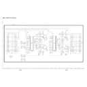
No sound (1) (Output from external terminals)
No Head phone sound output.
Are output from Pins (26)(27) of IC2514
(CODEC) and Pins (1)(7) of "HP-R/L-
IN"~IC2502 (HP_AMP) and the Q2501
(HP_MUTE) circuit normal?
Check the Headphone terminal (J2402) and
peripheral circuits.
No audio output from External Speakers.
(SPEAKER-
B
T
erminal)
In the
AUDIO-IF PWB : Is RELA
Y
(R
Y6000)
normally operated?
In the
AUDIO-IF PWB : Is the "H" signal
coming to "SP-SW" of Pin (1) of SF-
Connector?
In the
A
V
PWB : Is the "H" signal output to
Pin (6) of IC3808?
In the
A
V
PWB : Confirm IC3808 SDA3-1
LINE and peripheral circuits.
Is "Speaker Setup" in the MENU-Set up set
to "SPEAKER-B"?
If not, set the "SPEAKER-B".
No audio output from Optical-Audio-OUT
(IC1
109).
YES
YES
YES
YES
YES
YES
NO
NO
NO
YES
YES
Check the "HP-PLUG" signal Line.
Check Pin (4) of Headphone (J2402) thru
Pin (1
1) of IC2509.
Replace IC1
109 or check peripheral circuits.
Check the SPDIF signal from Pin (40) of
MA-Connector (P3802) and Pin (15) of B/B-
Connector (P8903).
Replace IC8903 or check peripheral circuits.
Replace IC8601 or check peripheral circuits.
Replace IC2507 (OPT
-SW) or check
peripheral circuits.
NO
NO
NO
NO
NO
Is output from Optical-Fiber
T
ransmitter
(IC1
109) normal?
Is input into Pin (12) of IC2507 (OPT
-SW)
normal?
In the DVB-T
PWB : Is output from Pin (2) of
IC8903 (INV) coming?
Is output from Pin (AC16) of IC8601
(Processor) normal?
Is output from Pin (8) of IC2507 (OPT
-SW)
normal?
(At digital broadcast reception)
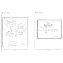
50
TU-45GD1E
LC-45GD1E
LC-45GD1E
TROUBLE SHOOTING TABLE
(Continued)
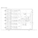
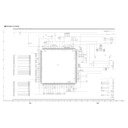
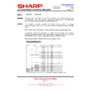
No sound (2) (On the reception of TV broadcasting)
No Display audio output.
1) Is a Headphone connected?
···Disconnect it.
2) In the MENU-Option, is "Audio Out" set to "Fixed"?
···Set it "Fixed".
3) In the MENU-Option, is "Centre Channel input" set to "of
f"?
···Set it "of
f".
4) In the MENU-Set up, is "Speaker Setup" set to "SPEAKER-A"?
···Set it "SPEAKER-A".
YES
NO
NO
NO
NO
YES
YES
YES
NO
In the
AUDIO-IF PWB : Is the
AUDIO
signal coming to RELA
Y
R
Y6000 and
R
Y6001?
In the
AUDIO-IF PWB : Is the
AUDIO
signal input to SC-Connector (P6003)?
Is the
AUDIO signal input to the 1 bit-
AMP
UNIT?
In the
A
V
UNIT
: Is the
AUDIO signal
output to Pins (27)(28) of IC2514?
Confirm IC2514 (CODEC), IC2501 (MSP)
and peripheral circuits.
Is the
AUDIO signal output to DISPLA
Y
-
OUTPUT3 (SC6001)?
Is the connection of System cable (black)
normal?
(Display Side)
Display Side : Is the
AUDIO signal input to
AUDIO-Connector (J2201) and SO-
Connector (P2201)?
Display Side : Is the connection of SO-
Connector (P202) and SP-terminal (P203)
in the SP-UNIT
normal?
Are the connection in the SP-KUMI and
the Speaker normal?
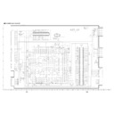
51
TU-45GD1E
LC-45GD1E
LC-45GD1E
TROUBLE SHOOTING TABLE
(Continued)
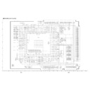
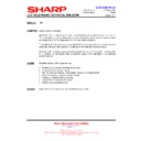
No sound (2) (On the reception of TV broadcasting)
Is the SIF audio signal input to Pins (67)(69)
of IC2501 (MSP)?
No audio output on the reception of
UHF/VHF
.
Is the SIF signal output from Pin (7) of
TUNER (TU1
101)?
Check the
TUNER (TU1
101) and its
peripheral circuits.
Check the signal LINE of Pins (33)(34) of
IC2501 thru Pins (32)(33) of IC2514 and
peripheral circuits.
YES
NO
NO
Check IC2514 and peripheral circuits.
Confirm the connection of 1 bit-AMP
and
replace it.
Check the SP-SW and 1B-RELA
Y
signals
are coming to Pins (1)(2) of SF connector
.
YES
YES
YES
YES
Is the audio signal of Pins (33)(34) of IC2501
(MSP) thru Pins (32)(33) of IC2514
(CODEC) normal?
Is each audio output from Pins (28)(29) of
IC2514 normal?
Is audio output of Pins (28)(29) of IC2514
thru 1 bit-AMP
input (SA/CNA101) normal?
Is output from 1 bit-AMP
(SC/CNA102)
normal?
Is connector of
AUDIO-I/F PWB (SC/P6003)
thru Relay switching of R
Y6001 (SPEAKER
ON/OFF switching) and R
Y6000 (SPEAKER
A/B switching) normal?
Check DISPLA
Y
-OUTPUT3 (SC6001) and
SYSTEM-CABLE (BLACK).
NO
YES
YES
NO
NO
NO
NO
No audio output on the reception of DTV
.
Is the MAIN-L/R signal of Pins (52)(54) of
IC3801 thru Pins (56)(57) of IC2501 coming
normally?
Is the DTV
-L/R signal coming to Pins
(59)(61) of IC3801 (A
V
-SW) normally?
DVB-T
UNIT
: Is the L/R audio signal output
from Pins (27)(29) of P8903?
Check IC3801 (A
V
-SW) and peripheral
circuits.
Confirm the connection of Pins (27) thru (29)
of MA-connector (P3802) and B/B (P8903).
Check IC8904 and peripheral circuits.
Check IC8905 and peripheral circuits.
YES
YES
YES
YES
NO
NO
NO
NO
NO
Is the L/R audio signal output to Pins
(91)(95) of IC8905?
Is the digital signal input to Pins (15-17)(19)
of IC8905?
Check IC8801-8802, IC8804-8805,IC8601
and peripheral circuits.
Check the connection of SA
connector and
to 1 bit-AMP
.
1) Is a Headphone connected?
···Disconnect it.
2) In the MENU-Option, is "Audio Out" set to "Fixed"?
···Set it "Fixed".
3) In the MENU-Option, is "Centre Channel input" set to "of
f"?
···Set it "of
f".
4) In the MENU-Set up, is "Speaker Setup" set to "SPEAKER-A"?
···Set it "SPEAKER-A".
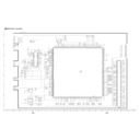
52
TU-45GD1E
LC-45GD1E
LC-45GD1E
TROUBLE SHOOTING TABLE
(Continued)
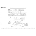
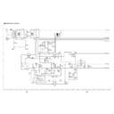
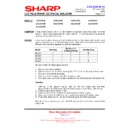
No picture (1)
No INPUT1 output of the external input
system.
Is "INPUT1" selected with the "INPUT
SOURCE"
button ( ) of the remote controller?
Check Pin (20) of SCAR
T1 (SC1
101) thru
Pins (1)(3) of IC3801.
Select "INPUT1" with the "INPUT
SOURCE" button ( ) of the remote
controller
, select Option-Input Select in the
MENU item, and then select Signal
T
ype of
the input signal.
YES
YES
YES
YES
YES
YES
YES
YES
YES
YES
YES
YES
Is the Composite V
ideo signal (CVS1) input
to input terminals Pins (1)(3) of IC3801 (A
V
-
SW)?
No INPUT2 output of the external input
system.
Is "INPUT2" selected with the "INPUT
SOURCE"
button ( ) of the remote controller?
Select "INPUT2" with the "INPUT
SOURCE" button
( ) of the remote controller
, select Option-
Input Select in the MENU item, and then select
Signal
T
ype of the input signal.
Check Pin (20) of SCAR
T2 (SC1
102) thru
Pins (8)(10) of IC3801.
Check IC3801 (A
V
-SW) and peripheral
circuits.
Check IC3801 (A
V
-SW) thru IC401/IC600.
Check IC600 (LPF) thru IC601 (VPC).
Check IC402 (3D-YC), IC502 (2D-YC) and
IC601 (VPC) thru IC3201 (L
VDS_TX), or
replace the main PWB.
Check IC3201 (L
VDS_TX) and peripheral
circuits.
Check IC3201 thru SC3200.
YES
YES
YES
YES
Is the Composite V
ideo signal (CVS2) input
to input terminals Pins (8)(10) of IC3801 (A
V
-
SW)?
<On input of the Composite V
ideo signal>
Are MAIN-V
ideo signal and SUB-V
ideo signal output to Pins (56) and (44) of IC3801 (A
V
-SW) respectively?
<On input of the Composite V
ideo signal>
Are MAIN-V
ideo signal and SUB-V
ideo signal input to Pin (8) of IC401 (LPF) and Pin (2) of IC600 (LPF) respectively?
Is the VIDEO signal input to input terminals
of Pin (8) of IC402 (3D-YC) and Pin (16) of
IC502 (2D-YC)?
(MAIN V
ideo System)
Is the digital video signal output from Pins
(124) thru (133) of IC402 and Pins (1
15) thru
(126) of IC502?
Are the digital video signal and H/V
-SYNC signal input to Pins (51) thru (78) and Pins (7) thru (10) of IC3201 (L
VDS_TX) respec
tively?
Is the digital video signal output to Pins (39) thru (49) of IC3201 (L
VDS_TX)?
Is the digital video signal(T
A
~
TD )output to Pins (2) thru (15) of L
V
Connector (SC3200)?
No problem in the MAIN PWB. Check the
TMDS PWB.
Is the input/output signal of Pins (9) thru (20) of IC3105 ~ Pins (21) thru (31) of IC3101 in the
TMDS PWB normal?
Are the Connector SC3102 of DISPLA
Y_OUTPUT1 and the SYSTEM_CABLE normal?
Check the LCD_DISPLA
Y
side.
NO
NO
NO
NO
NO
NO
NO
NO
NO
NO
NO
NO
NO
Check IC401 (LPF) thru IC402 (3D-
YC)/IC502 (2D-YC).
NO
Check IC402 (3D-YC), IC502 (2D-YC) and
peripheral circuits.
NO
YES
YES
Is the VIDEO signal input to the input
terminal Pin (72) of IC601 (VPC)?
(SUB V
ideo System)
Is the digital video signal output from Pins
(41) thru (50) of IC601?
Check IC601 (VPC) and peripheral circuits.
Check the input/output signal of
IC3105/IC3101 in the
TMDS PWB and
peripheral circuits.
Check the Connector SC3102 of
DISPLA
Y_OUTPUT1 and the
SYSTEM_CABLE.
+
+ -
-

