Sharp LC-37RD2E (serv.man6) Service Manual ▷ View online
LC-32RD2E/RU, LC-37RD2E/RU
6 – 3
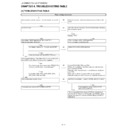
2. Detailed ICs Information
2.1. IC201 (VHiTDA9886+-1Y)
2.1.1 Block Diagram
2.1.2 Pin Connections and short description
Pin No.
Pin Name
I/O
Pin Function
1
VIF1
I
VIF differential input1
2
VIF2
I
VIF differential input2
3
OP1
O
Output1 (open-collector)
4
FMPLL
—
FM-PLL for loop filter
5
DEEM
O
De-emphasis output for capacitor
6
AFD
I
AF decoupling input for capacitor
7
DGND
—
Digital ground
8
AUD
O
Audio output
9
TOP
—
Tuner AGC TakeOver Point (TOP)
10
SDA
I/O
I2C-bus data input/output
11
SCL
I
I2C-bus clock input
12
SIOMAD
O
Sound intercarrier output and MAD select
13
N.C
—
Not connected
14
TAGC
O
TAGC14tuner AGC output
15
REF
I
4MHz crystal or reference input
16
VAGC
—
VIF-AGC for capacitor
17
CVBS
O
Video output
18
AGND
—
Analog ground
19
VPLL
—
VIF-PLL for loop filter
20
VP
—
Supply voltage (+5 V)
21
AFC
O
AFC output
22
OP2
O
Output2 (open-collector)
23
SIF1
I
SIF differential input1
24
SIF2
I
SIF differential input2
LC-32RD2E/RU, LC-37RD2E/RU
6 – 4
2.2. IC202 (RH-iXB964WJZZQ)
2.2.1 Pin Connections and short description
Pin No.
Pin Name
I/O
Pin Function
Clock and resets
32
32
NOT_RESET
I
Hardware reset, active low
15
XTAL_I
I
Analog Crystal oscillator input/external clock (2.5 V)
14
XTAL_O
O
Analog Crystal oscillator output
13
VDDA_2V5
—
Supply Analog oscillator supply (2.5 V)
16
VDDA_2V5
—
Supply Analog PLL supply (2.5 V)
Analog interface
1
1
RF_LEVEL
—
ADC 8 input for RF level monitoring
2
VDDA_2V5
—
Analog ADC 8 supply (2.5 V)
3
QP
—
Positive Q analog input for baseband configuration
4
QM
—
Negative Q analog input for baseband configuration
5
VDDA_ISO
—
Analog ISO nwell polarization (2.5 V)
6
VDDA_2V5
—
Analog ADC 12 supply (2.5 V)
7
REFP
—
Internal positive reference
8
REFM
—
Internal negative reference
9
INCM
—
Internal common mode
10
IM
—
Negative I analog input for IF and baseband configuration
11
IP
—
Positive I analog input for IF and baseband configuration
12
VDDA_1.0
—
Analog supply (1.0 V)
I2C interface
29
29
SDA
I/O
Serial data (open drain)
30
SCL
I
Serial clock (open drain)
21
SDAT
I/O
SDA tuner (open drain)
20
SCLT
I
SCL tuner
MPEG interface
43
43
D7
O
Serial MPEG data or parallel MPEG data (bit 7)
42
D6
O
Parallel MPEG data (bit 6)
40
D5
O
Parallel MPEG data (bit 5)
39
D4
O
Parallel MPEG data (bit 4)
37
D3
O
Parallel MPEG data (bit 3)
36
D2
O
Parallel MPEG data (bit 2)
35
D1
O
Parallel MPEG data (bit 1)
33
D0
O
Parallel MPEG data (bit 0)
44
CLK_OUT
O
MPEG byte or bit clock
46
STR_OUT
O
MPEG first byte sync
47
D/NOT_P
O
MPEG data valid/parity
48
ERROR
O
MPEG packet error
Front end controls
18
18
AGC_RF
I/O
RF AGC control
(5 V tolerant)
17
AGC_IF
I/O
IF AGC control
(5 V tolerant)
64
TEST
I/O
Reserved test mode, must be grounded.
27
GPIO0
I/O
General-purpose input/output port 0. Reserved test mode, must be grounded.
49
GPIO1
I/O
General-purpose input/output port 1
60
GPIO2
I/O
General-purpose input/output port 2 or lock indicator
59
GPIO3
I/O
General-purpose input/output port 3 or lock indicator
58
GPIO4
I/O
General-purpose input/output port 4
57
GPIO5
I/O
General-purpose input/output port 5
54
GPIO6
I/O
General-purpose input/output port 6
53
GPIO7
I/O
General-purpose input/output port 7
52
GPIO8
I/O
General-purpose input/output port 8. Reserved test mode, must be grounded.
61
GPIO9
I/O
General-purpose input/output port 9
23
AUX_CLK
I/O
Auxiliary clock
25
CS0
I
Chip select LSB
26
CS1
I
Chip select MSB
Power supply
19, 24, 31, 38,
45, 51, 55, 62
19, 24, 31, 38,
45, 51, 55, 62
VDD_1V0
—
Digital core supply (1.0 V)
22, 28, 34, 41,
50, 56, 63
50, 56, 63
VDD_3V3
—
Digital I/O supply (3.3 V)
LC-32RD2E/RU, LC-37RD2E/RU
6 – 5
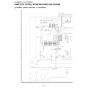
2.3. IC301/IC302 (VHiTDA8931T-1Y)
2.3.1 Block Diagram
LC-32RD2E/RU, LC-37RD2E/RU
6 – 6
2.3.2 Pin Connections and short description
Pin No.
Pin Name
Pin Function
1
VSSD
Negative digital supply voltage; heat spreader
2
VSSA
Negative analog supply voltage
3
INN
Inverting input
4
INP
Non inverting input
5
VDDA
Positive analog supply voltage
6
POWERUP
Power-up input
7
ENABLE
Enable input
8
DIAG
Diagnostic output
9
CGND
Control ground; reference ground for pins POWERUP, ENABLE and DIAG
10
VSSD
Negative digital supply voltage; heat spreader
11
VSSD
Negative digital supply voltage; heat spreader
12
OVP
Overvoltage protection reference input
13
HVP
Half supply voltage output for charging SE capacitor
14
STABI
Decoupling of internal stabilizer
15
VSSP
Negative power supply voltage
16
OUT
PWM output
17
BOOT
Bootstrap capacitor connection
18
VDDP
Positive power supply voltage
19
HVPI
Half supply voltage output for reference voltage of input circuitry
20
VSSD
Negative digital supply voltage; heat spreader

