Sharp LC-37HV4E (serv.man31) User Manual / Operation Manual ▷ View online
44
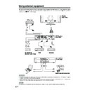
Using external equipment
AVC System (rear view)
DVD player
Component cable (commercially available)
SCART cable
(commercially available)
(commercially available)
When using component
cable, select
“COMPONENT” for “Input
Select” in the menu.
cable, select
“COMPONENT” for “Input
Select” in the menu.
Watching a DVD image
Connecting a DVD player
You can use the INPUT 3 terminal when connecting to a DVD player and other audiovisual equipment.
Displaying a DVD image
To watch a DVD image, select “INPUT3” from “INPUT
SOURCE” menu using b on the remote control unit
or INPUT on the Display.
SOURCE” menu using b on the remote control unit
or INPUT on the Display.
Then select “INPUT3” on “Input Select” in the menu to
set the correct input signal type. (See page 52.)
set the correct input signal type. (See page 52.)
The setting is stored and can be selected in the “INPUT
SOURCE” menu.
SOURCE” menu.
NOTE
• Each time b is pressed, the input source toggles.
• If the DVD image does not come in clearly, you may need
• If the DVD image does not come in clearly, you may need
to change the input signal type setting on the “Input Select”
menu.
menu.
• Refer to your DVD player operation manual for the signal
type.
TV MENU
Option
Input Select
COMPONENT
Y/C
CVBS
RGB
INPUT SOURCE
TV
INPUT1
INPUT2
INPUT3
INPUT4
PC
(For INPUT3 signal)
45
Using external equipment
AVC System (front view)
Game console/Camcorder
Composite video cable
(commercially available)
(commercially available)
S-video cable
(commercially available)
(commercially available)
Enjoying a game console and viewing camcorder images
Connecting a game console or camcorder
A game console, camcorder and some other audiovisual equipment are conveniently connected using the
INPUT 4 terminals.
INPUT 4 terminals.
NOTE
• The S-video terminal has priority over the video terminals.
Displaying an image of the game console or
camcorder
camcorder
To connect a game console or view a camcorder, select
“INPUT4” from the “INPUT SOURCE” menu using b
on the remote control unit or INPUT on the Display.
“INPUT4” from the “INPUT SOURCE” menu using b
on the remote control unit or INPUT on the Display.
Then select “INPUT4” on “Input Select” in the menu to
set the correct input signal type. (See page 52.)
set the correct input signal type. (See page 52.)
The setting is stored and can be selected on the
“INPUT SOURCE” menu.
“INPUT SOURCE” menu.
NOTE
• Each time b is pressed, the input source toggles.
INPUT SOURCE
TV
INPUT1
INPUT2
INPUT3
INPUT4
PC
TV MENU
Option
Input Select
AUTO
S-Video
Video
(For INPUT4 signal)
46
Using external equipment
RGB cable
(commercially available)
(commercially available)
AVC System (front view)
ø 3.5 mm stereo minijack cable
(commercially available)
(commercially available)
PC
15
14
13
12
9
11
10
8
7
6
5
4
3
2
1
Pin No.
Signal name
Pin No.
Signal name
Pin No.
Signal name
1
R
6
GND (Ground)
q
Not connected
2
G
7
GND (Ground)
w
SDA
3
B
8
GND (Ground)
e
HD
4
Not connected
9
+5V
r
VD
5
CSYNC
0
GND (Ground)
t
SCL
Viewing an image from a PC
Connecting a PC
Use the PC terminals to connect a PC.
NOTE
• The PC input terminals are DDC1/2B-compatible.
• Refer to page 68 for a list of PC signals compatible with the System.
• Refer to page 68 for a list of PC signals compatible with the System.
Signal names for 15-pin mini D-sub connecter
NOTE
• Macintosh adaptor may be required for use for some Macintosh computers.
Displaying an image from a PC
To view an image from a PC, select “PC” from the
“INPUT SOURCE” menu using b on the remote
control unit or INPUT on the Display.
“INPUT SOURCE” menu using b on the remote
control unit or INPUT on the Display.
When connecting to a PC, the correct input signal type
is automatically detected. (See page 56.) If the PC
image does not come in clearly, you may need to set
the Auto Sync. adjustment in the “Setup” menu. (See
page 51.)
is automatically detected. (See page 56.) If the PC
image does not come in clearly, you may need to set
the Auto Sync. adjustment in the “Setup” menu. (See
page 51.)
NOTE
• Each time b is pressed, the input source toggles.
INPUT SOURCE
TV
INPUT1
INPUT2
INPUT3
INPUT4
PC
47
Rear view
Using external equipment
Connecting external speakers
RED BLACKBLACK RED
When using external speakers
• Change the speaker setting to external speakers. (See
page 48.)
Make sure to connect the speaker jack and cable
polarity (L, +) properly
polarity (L, +) properly
• The speaker jacks have plus (L) and minus (+) polarity.
• Plus is red and minus is black.
• The cables are also divided into plus and minus.
• When connecting the left/right speakers, be sure to
• Plus is red and minus is black.
• The cables are also divided into plus and minus.
• When connecting the left/right speakers, be sure to
connect the plus/minus jacks with the correct cables.
NOTE
• See page 8 for bundling the cables of the external
speakers.
• Unplug the AC cord from the AC outlet before installing
the speakers.
How to connect the speaker cable
Pull up the lid.
Insert the edge of the
cable.
cable.
1
1
1
1
1
2
2
2
2
2
3
3
3
3
3
Put the lid back down.
• Bundle the cables of the external
speakers with clamps as shown above.
CAUTION
• Make sure external speakers have 8 ohm and 10 watt
specifications.
• Connect the plus/minus jacks with the correct cables.
Incorrect connection may cause a short.
Click on the first or last page to see other LC-37HV4E (serv.man31) service manuals if exist.

