Sharp LC-37GD1E (serv.man6) Service Manual ▷ View online
9
LC-32GD1E
LC-37GD1E
LC-37GD1E
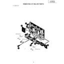
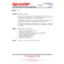
REMOVING OF MAJOR PARTS
LC-32GD1E
5
5
Terminal Cover
Terminal Cover
SP Terminal Cover
SP Terminal Cover
8
6
11
3
12
1
9
11
4
2
10
7
6
Stand
Speaker Box
Cabinet A
Cabinet B
Terminal Cover (Bottom)
Terminal Cover
(Top)
(Top)
SP Cable
(L)
(L)
SP Cable (R)
1. Remove the Terminal Covers
1
and
2
.
2. Disconnect the SP Cable (R)
3
from the SP terminal on the set.
3. Remove the 4 stand lock screws
4
and detach the Stand.
4. Remove the 4 bracket screws
5
and detach the Bracket.
5. Remove the SP Terminal Cover
6
and disconnect the SP Cable (L)
7
.
6. Remove the 4 speaker lock screws
8
and separate the Speaker Box from the set.
7. Remove the following screws: 13 M4 resin cabinet lock screws
9
, two M4 machine screws
0
, 3 M3
resin screws
q
and two M3 machine screws
w
. Then detach the Cabinet B.
10
LC-32GD1E
LC-37GD1E
LC-37GD1E
Wire Holder
13
Shield Plate
Earth Plate
14
FPC
Top Operaion Section Assembly
15
15
18
16
17
17
16
TMDS RX PWB
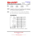
8. Remove the 13 Shield Plate mounting screws
e
, and detach the Shield Plate and the Wire Holder.
9. Remove the 2 top operation section assembly mounting screws
r
.
10. Disconnect the FPC. (with ferrite core)
11. Remove the 16 leads from fluorescent lights
t
.
12. Remove the 4 angles lock screws
y
.
13. Remove the 8 angles lock screws
u
.
14. Remove the 1 TMDS RX PWB unit screws
i
.
11
LC-32GD1E
LC-37GD1E
LC-37GD1E
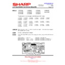
15. Remove the LCD CONT PWB mounting screw
o
to detach the LCD CONT PWB.
16. Remove the 6 POWER SUPPLY PWB mounting screws
p
to detach the POWER SUPPLY PWB.
17. Remove the 2 R/C LED PWB mounting screws
a
to detach the R/C LED PWB.
18. Remove the 4 INVERTER-A PWB mounting screws
s
to detach the INVERTER-A PWB.
19. Remove the 4 INVERTER-B PWB mounting screws
d
to detach the INVERTER-B PWB.
20. Remove the 3 INVERTER-A GND PWB mounting screws
f
to detach the INVERTER-A GND PWB.
21. Remove the 3 INVERTER-B GND PWB mounting screws
g
to detach the INVERTER-B GND PWB.
22. Remove the 4 MOTOR SP PWB mounting screws
h
to detach the MOTOR SP PWB.
23. Remove the 4 fan mounting screw
j
to detach the 2 fans.
24. Remove the 4 chassis mounting screws
k
, and remove the Backlight Chassis from Cabinet A.
INVERTER-A
GND PWB
GND PWB
INVERTER-B
GND PWB
GND PWB
INVERTER-B PWB
FAN
LCD CONT PWB
POWER SUPPLY PWB
MOTOR SP PWB
R/C LED PWB
INVERTER-A PWB
FAN
Backlight Chassis
Remove the connector.
26
23
21
25
24
27
27
22
28
28
19
28
28
20
12
LC-32GD1E
LC-37GD1E
LC-37GD1E
•
Precautions in handling the LCD panel
1. Handle the liquid crystal panel in a clean room (Humidity: 50% or more).
2. Be sure to wear an earth wristband.
3. Be careful not to drop and shock the liquid crystal panel.
4. Use an ionizer (within 30 cm).
25. Remove the 5 screws
l
(LX-BZA051WJFN).
26. Remove the LCD Panel Unit.
27. Remove the 8 screws
;
(LX-BZA052WJFN).
28. Remove the sheet presser angles.
29. Remove the 6 screws
31
(XBPSN30P10000).
30. Remove the sheet presser angles.
31. Detach the Reflection/Deflection Sheet, Prism Sheet, Diffusion Sheet, and Diffusion Plate.
32. Remove the 6 screws
32
(XBBSN30P08000).
33. Remove the 2 Lamp Holders (Top).
34. Detach the lamps.
*
The Reflection Plate (PMIR-S040WJZZ) is attached to the Backlight Chassis using clips and two-sided tape, and
it cannot be disassembled.
LCD Panel Unit
Reflection/Deflection Sheet
Diffusion Panel
Diffusion Sheet
Sheet Presser Angle
Prism Sheet
Lamp Holder (Top)
Lamp
Lamp Holder (Top)
Lamp Holder (Bottom)
Backlight Chassis
Lamp Holder (Bottom)
29
30
31
30
32
32
31
Display

