Sharp LC-37AD1E (serv.man9) Service Manual ▷ View online
41
LC-37AD1E
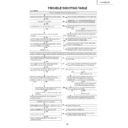
TROUBLE SHOOTING TABLE
Connect the power cord correctly and turn ON the power SW.
Is the power cord connector connected to the main body correctly?
Is there any faulty part or short-circuited circuit on the
BU+5V line?
BU+5V line?
Remove the faulty or short-circuited part and perform
checking again.
checking again.
Check the peripheral circuitry of IC1701.
Is the BU+5V line (pin (12) of P1702) normal?
Connect the wire harness, FFC, etc. in the set
correctly and perform checking again.
correctly and perform checking again.
Check the parts (IC701, IC721, PC702, Q702, Q703,
and D711) in the power unit.
and D711) in the power unit.
Are the wire harness, FFC, etc. in the set connected
correctly?
correctly?
Check each DC/DC converter output line and replace
MOS-FET (Q1701, Q1702, Q1703 and IC1706).
MOS-FET (Q1701, Q1702, Q1703 and IC1706).
Are each DC/DC converter output and MOS-FET (Q1701,
Q1702, Q1703 and IC1706) normal?
Q1702, Q1703 and IC1706) normal?
Replace IC1702.
Replace the fuse (F701). If the fuse blows when the power SW is
turned ON, replace D701 and IC 701 and perform checking again.
turned ON, replace D701 and IC 701 and perform checking again.
Is the fuse (F701) normal?
Power is not supplied. (The front LED does not go on.)
(AVC System)
Connect the connectors correctly and turn ON the
power again.
power again.
Are the connectors MDR (white) and DVI (gray) of the
system cable connecting the Display and AVC System
connected correctly?
system cable connecting the Display and AVC System
connected correctly?
Is PS_ON (pin (10) of P1702) set to "H" (3.5V)?
Check the PS_ON line.
Are the voltages on the UR+6V, UR+10V and UR+13V
lines (pins (7), (20) and (4) of P1702) normal?
lines (pins (7), (20) and (4) of P1702) normal?
Check the UR+6V, UR+10V and UR+13V
lines and the circuit parts on the lines.
lines and the circuit parts on the lines.
Are the D+1.8VCV (pins (5) and (6) of P1701) line,
D+3.3V (pin (8) of P1701) line, A+5V (pin (3) of P1701)
line and D+5V (pin (1) of P1701) line normal?
D+3.3V (pin (8) of P1701) line, A+5V (pin (3) of P1701)
line and D+5V (pin (1) of P1701) line normal?
Check if the wire harness, FFC, etc. in the set are
connected correctly.
connected correctly.
Check each output line and replace MOS-FET (Q1701,
Q1702 and Q1703) and REG IC (IC1704 and IC1705).
Q1702 and Q1703) and REG IC (IC1704 and IC1705).
Is D_POW (pins (32), (33) and (34) of IC1702, pin (2)
of IC1704 and pin (2) of IC1705) set to "H"?
of IC1704 and pin (2) of IC1705) set to "H"?
Check the line of D_POW (pin (6) of main PWB
IC1503).
IC1503).
Replace IC1702.
Turn ON the power SW on the AVC System side and the
power SW on the Display side and turn ON the power.
power SW on the Display side and turn ON the power.
Are the power SW on the AVC System side and the
power SW on the monitor side turned ON?
power SW on the monitor side turned ON?
Power is not supplied in spite of power-on operation being performed. (The front LED does not turn green from red or blinks in red.)
Check the UR+12V line.
Is power supplied to UR+12V (pins (5), (6), (7) and (8) of IC1781)?
Check the peripheral circuitry of IC1781 and Q1781
and the circuitry on the D+12V line.
and the circuitry on the D+12V line.
Is the D+12V line normal?
Check if the wire harness, FFC, etc. in the set are
connected correctly.
connected correctly.
Check the EU_D_POWER line.
Is EU_D_POWER (pin (17) of P1702) set to "H"?
EU DIGITAL power is not supplied.
Are the impedances of the UR+6V, UR+10V and
UR+13V lines normal?(Measure the resistances
between pins (7), (20) and (4) of P1702 and GND.)
UR+13V lines normal?(Measure the resistances
between pins (7), (20) and (4) of P1702 and GND.)
Are MOS-FET (Q1701, Q1702 and Q1703) and REG
IC (IC1704 and IC1705) normal?
IC (IC1704 and IC1705) normal?
Are there voltage variations on the OVP line (pin (18) of
P1702) just after the power is turned ON?
P1702) just after the power is turned ON?
NO
YES
NO
YES
NO
YES
YES
NO
NO
NO
NO
YES
YES
YES
NO
YES
NO
NO
YES
YES
YES
YES
NO
NO
NO
YES
NO
NO
YES
NO
YES
NO
YES
YES
NO
YES
42
LC-37AD1E
No sound comes out at the time of external input. (Sounds come out at the time of TV broadcast receiving.)
No sound comes out from the headphones.
Check or replace the peripheral circuitry of IC2501.
No sound comes out from the monitor
Perform checking from pins (25) and (24) of
IC2501(DACA L/R) to L.P.F (IC2506), H/P AMP
(IC2502) and audio mute (Q2501) and around
the headphone terminal (J2402).
Is the audio output from the monitor output
set to "Variable"? Are the headphones
connected?
Check the headphone mute circuit.
(Check the peripheral circuitry of D2501,
Q2501 and IC2502.)
Is the audio output from IC2501 (MULTI
SOUND PROCESSOR) normal?
Pins (34) and (33) of IC2501 (SC2 OUT L/R)
No sound comes out from the INPUT1 terminal.
No sound comes out from the INPUT2 and 3 terminals.
Is the audio output from IC2501 (MULTI SOUND
PROCESSOR) normal?
Pins (37) and (36) of IC2501 (SC1 OUT L/R)
Is the audio output from IC1301 (AV SWITCH)
normal?
Pins (43) and (45) of IC1301 (SC1 TV SUB
OUT L/R)
Perform checking from pins (37) and (36) of
IC2501 to pins (3) and (1) of SC1101
(IC2506, Q2517 and Q2516) and check the
audio mute circuit (Q1102 and Q1101).
Perform checking from pins (43) and (45) of
IC1301 to pins (3), (1), (24) and (22) of SC1102
(Q1106, Q1105, Q1111 and Q1110) and check
the audio mute circuit (Q1107, Q1104, Q1112
and Q1109).
Check the headphone plug circuit.
Perform checking from pin (4) of headphone
(J2402) to pin (77) of IC2501.
Perform checking from pins (34) and (33) of
IC2501 to pins (10) and (6) of the monitor
output terminal (J1101-) (IC2507, Q2503,
Q2502, Q1115 and Q1114) and check the
audio mute circuit (Q1116 and Q1117).
No sound comes out at the time of DTV receiving.
Check the display side.
No sound comes out at the time of UHF/VHF receiving.
Is the input signal to pins (59) and (61) of IC1301
(AV SW) normal?
Is the input signal to pin (67) (SOUND IF1)
and pin (69) (SOUND IF2) of IC2501
(MULTI SOUND PROCESSOR) normal?
Perform checking from pins (10) and (9) of
P2503 to pins (59) and (61) of IC1301 (AV
SW).
Is the input signal to pin (67) (SOUND IF1)
and pin (69) (SOUND IF2) of IC2501
(MULTI SOUND PROCESSOR) normal?
Is the I2S_DAOUT signal input normally from pin
(6) of IC2501 (MULTI SOUND PROCESSOR) to
pin (60) (12SDA1) of IC2510?
Is the audio output from IC2501 (MULTI
SOUND PROCESSOR) normal?
Pins (28) and (27) (DAC_M L/R) of IC2504
Is the audio output from pins (7) and (1) of
IC2504 (ACTIV FIL) normal?
Check if the I2S_DAOUT, I2S_CL, I2S_WS
and I2S_DAIN signals are output from IC2501
and input to IC2510 (DSP) normally.
Check IC2501 (MULTI SOUND
PROCESSOR) and the peripheral circuitry.
Check the peripheral circuitry of IC2504
(ACTIV FIL).
Is the SIF output from the tuner normal?
(Pin (21) of TU1101)
Check TU1101 (U/V tuner) and the parts
around it.
No sound comes out at the time of TV broadcast receiving. (Sounds come out at the time of external input.)
No sound comes out at the time of external input and PC input. (Sounds come out at the time of TV broadcast receiving.)
Is the audio input signal to IC1301 (AV
SWITCH) normal?
<INPUT1>
Pins (2) and (4) of IC1301 (L/R VIDEO1)
<INPUT2>
Pins (9) and (11) of IC1301 (L/R VIDEO2)
<INPUT3>
Pins (16) and (18) of IC1301(L/R VIDEO3)
<INPUT4>
Pins (23) and (25) of IC1301(L/R VIDEO4)
<PC SOUND INPUT>
Pins (29) and (31) of IC1301(L/R PC-IN)
Check IC1301 (AV SWITCH) and the
peripheral circuitry.
Check IC2501 (MULTI SOUND
PROCESSOR) and the peripheral circuitry.
Are the audio input circuits of IC1301 (AV
SWITCH) normal?
Perform checking from pins (6) and (2) of SC1101
to pins (2) and (4) (L/R VIDEO1) of IC1301.
Perform checking from pins (6) and (2) of SC1102
to pins (9) and (11) (L/R VIDEO2) of IC1301.
Perform checking from pins (27) and (23) of SC1102
to pins (16) and (18) (L/R VIDEO3) of IC1301.
Perform checking from pins (5) and (7) of J2404 to
pins (23) and (25) (L/R VIDEO4) of IC1301.
Perform checking from pins (2) and (3) of J2403 to
pins (29) and (31) (L/R PC-IN) of IC1301.
Is the audio output signal from IC1301 (AV
SWITCH) normal?
Is the audio input signal to IC2501 (MULTI
SOUND PROCESSOR) normal?
(AVC System)
YES
YES
YES
YES
NO
YES
YES
NO
NO
NO
NO
NO
NO
NO
YES
YES
YES
YES
YES
NO
YES
NO
YES
YES
43
LC-37AD1E
YES
No picture comes out at the time of external input. (Pictures come out at the time of TV broadcast receiving.)
<At the time of CVBS video signal input> Is the video signal input to pin (7) of IC401 (MAIN COMB FILTER)?
Check IC1301 (AV SWITCH) and the peripheral circuitry.
No TUNER (U/V) picture comes out.
No external input picture comes out. <<INPUT1>>
Is INPUT1 selected on the input change
menu screen?
Select an input signal on the input signal
source menu screen.
Is the signal input to each input terminal
of IC1301 (AV SWITCH)?
<CVBS video signal input>
Is the signal input to pin (1)?
<Y/C video signal input>
Are the Y and C signals input to pins (3)
and (5), respectively?
<At the time of CVBS video signal
input>
Are the MAIN-Y and MAIN-C signals
input to pins (5) and (7) of IC801 (MAIN
VIDEO CHROMA), respectively?
<At the time of Y/C video signal input>
Are the MAIN-Y and MAIN-C signals
input to pins (44) and (43) of IC801
(MAIN VIDEO CHROMA), respectively?
Are the Y, Cb and Cr MAIN signals output
to pins (21), (22) and (23) of IC801?
Are the Y, Cb and Cr MAIN signals input to pins
(69), (68) and (67) of IC803 (RGB DECODER)?
Are the R, G and B MAIN signals output
to pins (35), (37) and (39) of IC803?
Are the R, G and B MAIN signals input to pins
(25), (1) and (5) of FL810 (30/6.7MHz L.P.F.)?
Are the R, G and B MAIN signals output
to TP816, TP815 and TP814?
Check PC I/F Unit
Perform checking from IC1301 to IC401.
Perform checking from IC1301 to IC1551.
(Q409, Q410, Q828, etc.)
Check IC801 (MAIN VIDEO CHROMA)
and the peripheral circuitry.
Are the SUB-Y and SUB-C signals input to pins
(1) of IC1550 (VIDEO DRIVER) and pin (1) of
IC1551 (VIDEO DRIVER), respectively?
Is the video signal (CVBS) input to pin
(63) of IC1301 (AV SWITCH)?
Is the signal output to the video output
terminal (pin (23)) of the tuner?
Is the video signal output from the tuner to
TP2509?
Perform checking from the video output
terminal (pin (23)) of the tuner to pin (63)
of IC1301 (AV SWITCH).
Are the SUB-Y and SUB-C signals output to
pins (6) and (7) of IC1550 and pins (6) and
(7) of IC1551, respectively?
Check IC1550, IC1551 and the peripheral
circuitry.
Check the tuner and peripheral
circuitry.
Check PC I/F Unit
Perform checking from IC801 to IC803.
(Q842-4, IC813, IC814-6, etc.)
Check IC803 (RGB DECODER) and the
peripheral circuitry.
Perform checking from IC803 to FL810.
(Q801-3, etc.)
Is pin (21) of FL810 (30/6.7MHz L.P.F.) set to
"L"? Check the peripheral circuitry of FL810.
<CVBS video signal input>
Perform checking from pin (20)
of SC1101 to pin (1) of IC1301.
<Y/C video signal input>
Perform checking from pins (20)
and (15) of SC1101 to pins (3)
and (5) of IC1301.
<At the time of CVBS video signal input> Is the CVBS video signal output to pin (56) of IC1301?
<At the time of Y/C video signal input> Are the MAIN-Y, MAIN-C, SUB-Y and SUB-C signals output to pins (56), (58), (44) and (47
) of IC1301, respectively?
(AVC System)
<<MAIN system>>
<<SUB system>> <Y/C video signal>
<At the time of CVBS video signal and Y/C video signal input>
No external input picture comes out. <<INPUT2>>
Is INPUT2 selected on the input change
menu screen?
Select an input signal on the input signal
source menu screen.
Is the signal input to each input terminal
of IC1301 (AV SWITCH)?
<CVBS video signal input>
Is the signal input to pin (8)?
<Y/C video signal input>
Are the Y and C signals input to pins
(10) and (12), respectively?
Perform checking from pin
(20) of SC1102 to pin (8) of
IC1301.
Perform checking from pins
(15) and (20) of SC1102 to
pins (10) and (12) of
IC1301.
YES
No external input picture comes out. <<INPUT3>>
Is INPUT3 selected on the input change
menu screen?
Select an input signal on the input signal
source menu screen.
Is the signal input to each input terminal
of IC1301 (AV SWITCH)?
<CVBS video signal input>
Is the signal input to pin (15)?
<Y/C video signal input>
Are the Y and C signals input to pins
(17) and (19), respectively?
Perform checking from pin
(41) of SC1102 to pin (15) of
IC1301.
Perform checking from pins
(36) and (41) of SC1102 to
pins (17) and (19) of
IC1301.
No external input picture comes out. <<INPUT4>>
Is INPUT4 selected on the input change
menu screen?
Select an input signal on the input signal
source menu screen.
Is the signal input to each input terminal
of IC1301 (AV SWITCH)?
<CVBS video signal input>
Is the signal input to pin (22)?
<Y/C video signal input>
Are the Y and C signals input to pins
(24) and (26), respectively?
Perform checking from pin
(2) of J2404 to pin (22) of
IC1301.
Perform checking from pins
(3) and (4) of J2401 to pins
(24) and (26) of IC1301.
<At the time of CVBS video signal
input>
Perform checking from IC1301 to
IC801.(IC401, IC403, Q827, Q401-2,
Q415, etc.)
<At the time of Y/C video signal input>
Perform checking from IC1301 to
IC801.(Q404, Q403, etc.)
YES
YES
YES
YES
YES
YES
YES
YES
NO
NO
YES
NO
NO
NO
NO
NO
NO
NO
NO
YES
YES
YES
YES
NO
NO
NO
NO
YES
YES
YES
YES
NO
YES
NO
YES
NO
YES
NO
YES
44
LC-37AD1E
YES
Check PC I/F Unit
YES
Are the R, G and B MAIN signals output to
TP816, TP815 and TP814, respectively?
YES
Are the R, G and B MAIN signals input to pins (25), (1)
and (5) of FL810 (30/6.7MHz L.P.F.), respectively?
Is pin (21) of FL810 (30/6.7MHz L.P.F.) set to
"H"? Check the peripheral circuitry of FL810.
Perform checking from IC803 to FL810. (Q801-
803, etc.)
No external input picture comes out.
〈〈
INPUT1 SCART
〉〉
Perform checking from pins (7), (11)
and (15) of SC1101 to pins (59), (61)
and (63) of IC1401.
Is INPUT1 selected on the input change menu screen?
Select an input signal on the input signal source menu
screen.
YES
YES
NO
(AVC System)
〈〈
MAIN system
〉〉
〈〈
SUB system
〉〉
Is the signal input to each input terminal of
IC1401 (AV SWITCH)?
Are the G1, B1 and R1 signals input to pins
(59), (61) and (63), respectively?
Perform checking from pins (50), (48) and (46)
of IC1401 to pins (26) and (19), pins (25) and
(18) and pins (27) and (17) of IC801.
YES
YES
NO
Are the COMP_Y, CB and CR signals input to pins
(26) and (19), pins (25) and (18) and pins (27) and (17)
of IC801 (MAIN _VIDEO_CHROMA), respectively?
〈〈
PASS system
〉〉
Perform checking from pins (38), (36) and
(34) of IC1401 to pin (5) and (47), pins (4)
and (48) and pins (3) and (46) of IC803.
YES
YES
NO
Are the COMP3_Y, CB and CR signals input to pins
(5) and (47), pins (4) and (48) and pins (3) and (46)
of IC803 (RGB DECODER), respectively?
Check IC801 (MAIN VIDEO CHROMA)
and the peripheral circuitry.
YES
NO
Are the Y, Cb and Cr MAIN signals output to
pins (21), (22) and (23) of IC801, respectively?
Perform checking from pins (44), (42)
and (40) of IC1401 to pins (21), (24)
and (18) of SC1550.
YES
YES
NO
Are the COMP2_Y, CB and CR signals output
to pins (21), (24) and (18) of SC1550,
respectively?
NO
Check IC1401 (AV SWITCH) and the peripheral
circuitry.
Check PC I/F Unit
Perform checking from IC801 to IC803.
YES
NO
NO
NO
NO
Are the Y, Cb and Cr MAIN signals input to pins
(11) and (69), pins (10) and (68) and pins (9) and
(67) of IC803 (RGB DECODER), respectively?
Are the R, G and B MAIN signals output to pins (35), (37) and (39) of IC803, respectively?
Check IC803 (RGB DECODER) and the peripheral circuitry.
No external input picture comes out.
〈〈
INPUT3 SCART
〉〉
Are the G3, B3 and R3 signals input to pins (5), (7) and (9) of IC1401 (AV SWITCH), respectively?
Perform checking from pins (3), (5) and (6) of IC1401 to pins (5), (7) and (9) of IC1401.
Perform checking from pins (26), (32)
and (36) of SC1102 to pins (1), (14)
and (9) of IC2508.
Is INPUT3 selected on the input change menu screen?
Select an input signal on the input signal source menu
screen.
YES
YES
YES
NO
NO
Is the signal input to each input terminal of
IC2508 (COMPONENT_SEL)?
Are the G3, B3 and R3 signals input to pins (1),
(14) and (9), respectively?
No external input picture comes out.
〈〈
INPUT3 Y/Pb(Cr)/Pr(Cr)
〉〉
Perform checking from pins (3), (8)
and (12) of J1101 to pins (16), (11)
and (8) of IC2508.
Is INPUT3 selected on the input change menu screen?
Select an input signal on the input signal source menu
screen.
YES
YES
NO
Is the signal input to each input terminal of
IC2508 (COMPONENT_SEL)?
Are the Y, Pb and Pr signals input to pins (16),
(11) and (8), respectively?
No TUNER (DTV) picture comes out.
Perform checking from pins (19), (17)
and (15) of P2503 to pins (19), (17)
and (15) of IC1401.
Is DTV selected on the input change menu screen?
YES
YES
NO
Is the signal input to each input terminal of
IC1401 (AV SWITCH)?
Are the D_B, D_G and D_R signals input to
pins (19), (17) and (15), respectively?
Are the MAIN, PASS and SUB video signals output to pins (50), (48) and (46), pins (38), (36) and (34) and pins (44), (42) and (
40) of IC1401, respectively?
No picture comes out at the time of external input. (Pictures come out at the time of TV broadcast receiving.)
<At the time of RGB/COMPONENT video signal input>

