Sharp LC-32P55E (serv.man41) Service Manual ▷ View online
61
LC-26GA5E
LC-32GA5E
LC-26P55E
LC-32P55E
LC-37P55E
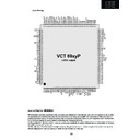
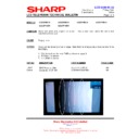
VCT 69xyP
ADVANCE INFORMATION
Volume 1: General Description
1-70
November 3, 2004; 6251-644-1-1
AI
Micronas
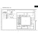
VCT 69xyP
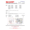
LVDS output
1 2 3 4 5 6 7 8 9 10 11 12 13 14 15 16 17 18 19 20 21 22 23 24 25 26 27 28 29 30 31 32 33 34 35 36 37 38 39 40 41 42 43 44 45 46 47 48 49 50 51 52
15
4
15
3
15
2
15
1
15
0
14
9
14
8
14
7
14
6
14
5
14
5
14
4
14
3
14
2
14
1
14
0
13
9
13
8
13
7
13
6
13
5
13
4
13
3
13
2
13
1
13
0
12
9
12
8
12
7
12
6
12
5
12
4
12
3
12
2
12
1
12
0
11
9
11
8
11
7
11
6
11
5
11
4
11
3
11
2
11
1
11
0
10
9
10
8
10
7
10
6
10
5
15
6
104
103
102
101
100
99
98
97
96
95
94
93
92
91
90
89
88
87
86
85
84
83
82
81
80
79
78
77
76
75
74
73
72
71
70
69
68
67
66
65
64
63
62
61
60
59
58
57
56
55
55
54
53
65
6O
6
65
6O
5
65
6O
4
65
6O
3
65
6O
2
65
6O
1
65
6O
0
R
E
S
E
T
Q
A
IN
1R
A
IN
1L
A
IN
2R
A
IN
2L
A
IN
3R
A
IN
3L
A
IN
4R
A
IN
4L
V
R
E
F
A
U
V
S
U
P
8.
O
A
U
A
O
U
T
2R
A
O
U
T
2L
A
O
U
T
1R
S
G
N
D
G
N
D
A
A
O
U
T
1L
H
E
A
D
P
H
O
N
E
R
H
E
A
D
P
H
O
N
E
L
S
P
E
A
K
E
R
R
S
U
B
W
O
O
F
E
R
V
R
E
F
S
IF
S
IF
IN
+
S
IF
IN
-
S
P
E
A
K
E
R
L
V
S
U
P
5.
0S
IF
G
N
D
A
G
N
D
3.
3D
IG
V
S
U
P
3.
3D
IG
S
P
D
IF
_O
U
T
I2
S
_D
A
_I
N
I2
S
_D
E
L
_O
U
T
I2
S
_D
E
L
_I
N
I2
S
_D
E
L
_C
L
I2
S
_W
S
I2
S
_C
L
I2
S
_D
E
L
_W
S
V
S
U
P
3.
3R
A
M
G
N
D
3.
3R
A
M
D
V
S
D
C
L
K
D
R
I7
D
R
I6
D
R
I5
D
E
N
V
S
U
P
1.
8D
IG
G
N
D
1.
8D
IG
V
S
U
P
3.
3L
V
D
S
L
V
D
S
A
_4
P
P
C
L
K
1
P
C
L
K
2
P
C
S
0
P
C
S
1
P
C
S
4
P
C
S
5
V
S
U
P
3.
3I
O
1
P
C
S
3
P
C
S
2
G
N
D
3.
3I
O
1
O
S
D
R
0
O
S
D
R
1
O
S
D
R
2
O
S
D
G
0
O
S
D
G
1
O
S
D
G
2
O
S
D
G
3
O
S
D
R
3
L
V
D
S
A
_4
N
G
N
D
3.
3L
V
D
S
L
V
D
S
A
_3
P
L
V
D
S
A
_3
N
V
S
U
P
3.
3L
V
D
S
L
V
D
S
A
_C
L
K
P
L
V
D
S
A
_C
L
K
N
G
N
D
3.
3L
V
D
S
L
V
D
S
A
_2
P
L
V
D
S
A
_2
N
V
S
U
P
3.
3L
V
D
S
L
V
D
S
A
_1
P
L
V
D
S
A
_1
N
V
S
U
P
1.
8L
V
D
S
L
V
D
S
A
_0
P
L
V
D
S
A
_0
N
G
N
D
1.
8L
V
D
S
R
E
X
T
L
V
D
S
B
_3
P
G
N
D
3.
3L
V
D
S
L
V
D
S
B
_3
N
V
S
U
P
3.
3L
V
D
S
L
V
D
S
B
_C
L
K
P
L
V
D
S
B
_C
L
K
N
G
N
D
3.
3L
V
D
S
L
V
D
S
B
_2
P
L
V
D
S
B
_2
N
V
S
U
P
3.
3L
V
D
S
L
V
D
S
B
_1
P
L
V
D
S
B
_1
N
VIN16
VIN15
VIN13
VIN12
VIN11
VIN9
VIN8
VIN6
VIN5
VIN3
VIN2
VIN7
VIN1
VIN22
VIN21
VIN20
VIN19
VIN17
VIN18
GNDA
VSUP1.8FE
VSUP3.3VO
VOUT3
VOUT2
VSUP3.3IO3
656I0
656I1
GND3.3IO3
VOUT1
656I2
656I3
656I4
656I5
656I7
656CLKI
656CLKO
656O7
656I6
P1_7
P1_6
P1_5
P1_4
GND3.3DAC
VSUP3.3DAC
P1_3
P1_2
P1_1
P1_0
VSUP1.8FE
VSUP3.3FE
LVDSB_0P
LVDSB_0N
CLKOUT
SDA
SCL
XTALOUT
XTALIN
HSO
VSO
GND3.3COM
VSUP3.3DRI
GND3.3DRI
DBI0
VSUP3.3COM
DBI1
OSDB0
OSDB1
OSDB2
OSDB3
OSDHCS0
OSDHCS1
OSDFSW
OSDCLK
VSUP3.3IO1
GND3.3IO1
OSDH
OSDV
P2_5
P2_4
P2_3
P2_2
P2_1
P2_0
GND3.3FL
VSUP3.3FL
DBI2
DBI3
DBI4
DBI5
DBI6
DGI1
DGI2
DGI3
DGI0
DBI7
DGI4
DGI5
DGI6
DGI7
DRI1
DRI2
DRI3
DRI4
DRI0
157
158
159
160
161
162
163
164
165
166
167
168
169
170
171
172
173
174
175
176
177
178
179
180
181
182
183
184
185
186
187
188
189
190
191
191
192
193
194
195
196
197
198
199
200
200
201
202
203
204
205
206
206
207
208
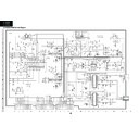
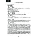
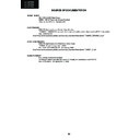
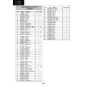
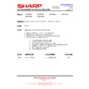
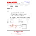
2.2.3. Pinning
Important Note from MICRONAS:
All information and data contained in the data sheet are without any commitment, are not to be considered as an offer
for conclusion of a contract, not shall they be construed as to create any liability. Any new issue of this data sheet in-
validates previous issues. Product availability and delivery are exclusively subject to our respective order confirmation
form; the same applies to orders based on development samples delivered.
By this publication, Micronas GmbH does not assume responsibility for patent infringements or other rights of third par-
ties which may result from its use.
Further, Micronas GmbH reserves the right to revise this publication and to make changes to its content, at any time,
without obligation to notify any person or entity of such revisions or changes.
62
LC-26GA5E
LC-32GA5E
LC-26P55E
LC-32P55E
LC-37P55E
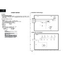
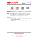
2.3. IC301, IC302 (VHITDA8931T-1Y)
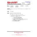
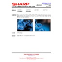
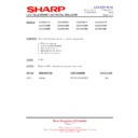
2.3.1. Block Diagram
9397 750 13847
© Koninklijke Philips Electronics N.V. 2005. All rights reserved.
Preliminary data sheet
Rev. 01 — 14 January 2004
3 of 31
Philips Semiconductors
TDA8931
Power comparator 1
× 20 W
6. Block diagram
Fig 1. Block diagram
001aab807
TDA8931
UVP
HEAT SPREADER
CONTROL
comparator
CONTROL
DRIVER
HIGH
STABILIZER
12V
BOOT
V
V
DDP
17
18
18
OUT
16
V
SSP
15
STABI
V
SSD
V
DDP
V
SSP
14
HVP
13
V
DDP
V
SSP
HVPI
19
DIAG
8
12
1
10
11
20
V
SSD
V
SSD
V
SSD
V
SSD
DRIVER
LOW
OVP
OVP
9
CGND
7
ENABLE
6
POWERUP
3
INN
4
INP
OCP
OTP
2
V
SSA
5
V
DDA
ODP
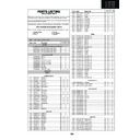
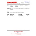
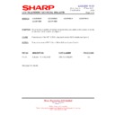
2.3.2. Pinning
9397 750 13847
© Koninklijke Philips Electronics N.V. 2005. All rights reserved.
Preliminary data sheet
Rev. 01 — 14 January 2004
4 of 31
Philips Semiconductors
TDA8931
Power comparator 1
× 20 W
7. Pinning information
7.1 Pinning
7.2 Pin description
Fig 2. Pin configuration
TDA8931
V
SSD
V
SSD
V
SSA
HVPI
INN
V
DDP
INP
BOOT
V
DDA
OUT
POWERUP
V
SSP
ENABLE
STABI
DIAG
HVP
CGND
OVP
V
SSD
V
SSD
001aab811
1
2
3
4
5
6
7
8
9
2
3
4
5
6
7
8
9
10
12
11
11
14
13
13
16
15
15
18
17
17
20
19
19
Table 3:
Pin description
Symbol
Pin
Description
V
SSD
1
negative digital supply voltage; heat spreader
V
SSA
2
negative analog supply voltage
INN
3
inverting input
INP
4
non inverting input
V
DDA
5
positive analog supply voltage
POWERUP
6
power-up input
ENABLE
7
enable input
DIAG
8
diagnostic output
CGND
9
control ground; reference ground for pins POWERUP, ENABLE and DIAG
V
SSD
10
negative digital supply voltage; heat spreader
V
SSD
11
negative digital supply voltage; heat spreader
OVP
12
overvoltage protection reference input
HVP
13
half supply voltage output for charging SE capacitor
STABI
14
decoupling of internal stabilizer
V
SSP
15
negative power supply voltage
OUT
16
PWM output
BOOT
17
bootstrap capacitor connection
V
DDP
18
positive power supply voltage
HVPI
19
half supply voltage output for reference voltage of input circuitry
V
SSD
20
negative digital supply voltage; heat spreader
63
LC-26GA5E
LC-32GA5E
LC-26P55E
LC-32P55E
LC-37P55E
2.4. IC201 (VHITDA9886+-1Y)
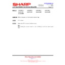
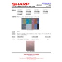
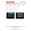
2.4.1. Block Diagram
2003 Oct 02
7
Philips Semiconductors
Product specification
I
2
C-bus controlled single and multistandard
alignment-free IF-PLL demodulators
TDA9885; TDA9886
This text is here in white to force landscape pages to be rotat
ed correctly when browsing through the pdf in the Acrobat reade
r.This text is here in
_
white
to
force
landscape
pages
to
be
rotated
correctly
when
browsing
through
the
pdf
in
the
Acrobat
reader.This
text
is
here
inThis
text
is
here
in
white
to
force
landscape
pages
to
be
rotated
correctly
when
browsing
through
the
pdf
in
the
Acrobat
reader.
white
to
force
landscape
pages
to
be
...
6
BLOCK DIAGRAM
handbook, full pagewidth
MHC108
DIGITAL VCO CONTROL
AFC DETECTOR
RC VCO
VIF-PLL
VIF-AGC
TUNER AGC
SUPPLY
SIF-AGC
AUDIO PROCESSING
AND SWITCHES
NARROW-BAND
FM-PLL DEMODULATOR
SINGLE REFERENCE QSS MIXER
INTERCARRIER MIXER
AND AM DEMODULATOR
SOUND CARRIER
TRAPS
4.5 to 6.5 MHz
TAGC
C
VAGC(pos)
C
AGC(neg)
C
BL
VAGC
(1)
TOP
14 (15)
VPLL
19 (21)
9 (8)
16 (17)
15 (16)
21 (23)
4 (2)
10 (9)
11 (10)
12 (11)
18 (20)
20 (22)
2 (31)
1 (30)
(18) 17
(7) 8
(3) 5
(4) 6
external reference signal
or 4 MHz crystal
REF
AFC
AUD
CVBS
audio output
video output
: 2 V (p-p)
[1.1 V (p-p) without trap]
C
AF
SIOMAD
SDA
SCL
MAD
V
P
C
AGC
(6, 12, 13, 14, 17,
19, 25, 28, 29, 32)
13
n.c.
AGND
7 (5)
DGND
OUTPUT
PORTS
I
2
C-BUS TRANSCEIVER
22 (24)
3 (1)
OP1
OP2
FMPLL
DEEM
AFD
sound intercarrier output
and MAD select
FM-PLL
filter
VIF-PLL
filter
de-emphasis
network
VIF2
VIF1
24 (27)
23 (26)
SIF2
SIF1
TDA9885
TDA9886
Fig.1 Block diagram.
(1)
Not connected for TDA9885.
Pin numbers for TDA9885HN and TDA9886HN in parenthesis.
64
LC-26GA5E
LC-32GA5E
LC-26P55E
LC-32P55E
LC-37P55E
2003 Oct 02
8
Philips Semiconductors
Product specification
I
2
C-bus controlled single and multistandard
alignment-free IF-PLL demodulators
TDA9885; TDA9886
7
PINNING
SYMBOL
PIN
DESCRIPTION
TDA9885T
TDA9885TS
TDA9886T
TDA9886TS
TDA9885HN TDA9886HN
VIF1
1
1
30
30
VIF differential input 1
VIF2
2
2
31
31
VIF differential input 2
n.c.
−
−
32
32
not connected
OP1
3
3
1
1
output port 1; open-collector
FMPLL
4
4
2
2
FM-PLL for loop filter
DEEM
5
5
3
3
de-emphasis output for capacitor
AFD
6
6
4
4
AF decoupling input for capacitor
DGND
7
7
5
5
digital ground
n.c.
−
−
6
6
not connected
AUD
8
8
7
7
audio output
TOP
9
9
8
8
tuner AGC TakeOver Point (TOP) for resistor
adjustment
adjustment
SDA
10
10
9
9
I
2
C-bus data input and output
SCL
11
11
10
10
I
2
C-bus clock input
SIOMAD
12
12
11
11
sound intercarrier output and MAD select with
resistor
resistor
n.c.
−
−
12
12
not connected
n.c.
13
13
13
13
not connected
n.c.
−
−
14
14
not connected
TAGC
14
14
15
15
tuner AGC output
REF
15
15
16
16
4 MHz crystal or reference signal input
VAGC
−
16
−
17
VIF-AGC for capacitor
n.c.
16
−
17
−
not connected
CVBS
17
17
18
18
composite video output
n.c.
−
−
19
19
not connected
AGND
18
18
20
20
analog ground
VPLL
19
19
21
21
VIF-PLL for loop filter
V
P
20
20
22
22
supply voltage
AFC
21
21
23
23
AFC output
OP2
22
22
24
24
output port 2; open-collector
n.c.
−
−
25
25
not connected
SIF1
23
23
26
26
SIF differential input 1 and MAD select with
resistor
resistor
SIF2
24
24
27
27
SIF differential input 2 and MAD select with
resistor
resistor
n.c.
−
−
28
28
not connected
n.c.
−
−
29
29
not connected
2.4.2. Pinning

