Sharp LC-32DH57E (serv.man5) Service Manual ▷ View online
LC-32DH57E-BK/RU-BK/S-BK
4 – 1
LC-32DH57E-BK
Service Manual
CHAPTER 4.
TROUBLESHOOTING TABLE
[1] TROUBLESHOOTING TABLE
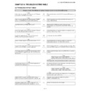
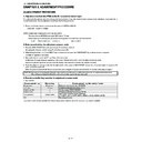
No power supplied (Front LED does not light up). No power-up even if turned on (Front LED light up)
YES
Is the power cord connector, AC-IN harness, and PD harness
connected to the POWER unit normally?
connected to the POWER unit normally?
NO
Reconnect the power cord, the AC-IN harness and PD harness cor-
rectly.
rectly.
YES
Is the connection of B to B connector between the POWER
unit and the INVERTER unit normal? (P7201-CN7302)
unit and the INVERTER unit normal? (P7201-CN7302)
NO
Correct connection or the short circuit of a B to B connector nor-
mally. (P7201-CN7302)
mally. (P7201-CN7302)
YES
Are F7001 (3.15A) and F7002 (3.15A) normal?
NO
Replace F7001 or F7002 and switch on the power again.
If Fuse still blow out, check L7001, L7002, D7104, VA7001, and
VA7002.
If Fuse still blow out, check L7001, L7002, D7104, VA7001, and
VA7002.
YES
Is DC310V supplied to the primary side capacitor C7114 and
C7108, when the power switch is turned on?
C7108, when the power switch is turned on?
NO
Check whether there are any abnormalities in a rectification circuit.
(D7104, C7114, C7108, L7101)
(D7104, C7114, C7108, L7101)
YES
Is UR12.5V supplied from pin (13) (14) of PD connector
(P7202), when the power switch is turned on?
(P7202), when the power switch is turned on?
YES
(*1) fly to the check item of INV60V.
NO
Is about DC400V supplied to primary side capacitor C7112?
NO
Check whether there are any abnormalities in a power factor
improvement circuit. (IC7101, Q7103, D7113, D7213)
improvement circuit. (IC7101, Q7103, D7113, D7213)
YES
Check whether the PS_ON “H” signal is inputted to the pin (6)
of PD connector (P7202) in the power supply unit.
of PD connector (P7202) in the power supply unit.
NO
Check whether the PS_ON “H” signal is outputted to pin (10) of PD
connector (P9601) and pin (AC11) of IC3303 (VCT) in the MAIN unit.
connector (P9601) and pin (AC11) of IC3303 (VCT) in the MAIN unit.
YES
Check again after remove parts which have trouble or a short
circuit. Is UR12.5V supplied from pin (13) (14) of PD connec-
tor (P7202)?
circuit. Is UR12.5V supplied from pin (13) (14) of PD connec-
tor (P7202)?
NO
Is there a part which breaks down on the UR12.5V line or short-cir-
culated?
culated?
YES
YES
NO
Check the power control circuit of UR12.5V.
(IC7201, T7206, D7217, C7220, C7222, C7228, D7215)
(IC7201, T7206, D7217, C7220, C7222, C7228, D7215)
Check again after remove parts which have trouble or a short circuit.
After the power supply is turned on, is INV60V generated in
connector P7201 (20-23) pin? (*1)
connector P7201 (20-23) pin? (*1)
NO
Is connector CN7302 of the INV unit removed, and is INV60V gener-
ated in connector P7201 (20-23) pin?
ated in connector P7201 (20-23) pin?
YES
YES
NO
Check the inverter power circuit of INV60V.
(D7227, C7221, C7223, T7206, D7220, D7221)
(D7227, C7221, C7223, T7206, D7220, D7221)
It is failure inside an INV unit. check broken parts or a shorting part.
(Q7809, Q7807, Q7811, Q7810, etc.)
(Q7809, Q7807, Q7811, Q7810, etc.)
Is BU3.3V/D3.3V supplied to pin (5) (6) of RA connector
(P3301) in a main unit, and pin (1) (2) of P101 in the R/C unit?
(P3301) in a main unit, and pin (1) (2) of P101 in the R/C unit?
NO
Check the power supply circuit of BU3.3V and D3.3V.
(IC9605, IC9607/IC9602, etc.)
(IC9605, IC9607/IC9602, etc.)
YES
“No power supplied (Front LED does not light up)”. “No
power-up even if turned on (Front LED light up).” Is it OK?
power-up even if turned on (Front LED light up).” Is it OK?
NO
Review the former step and check it again.
LC-32DH57E-BK/RU-BK/S-BK
4 – 2
Power supply (troubleshooting): A power supply does not come to each main circuit/IC. (1)
The power supply of TUNER (TU1102) does not operate.
(IF5V)
Checklist
1) The check of the front page POW-UNIT is completed.
••• UR12.5V is output to PD (P9601) (MAIN-UNIT).
(If UR12.5V is not output, confirm the POW-UNIT again and repair.)
2) Check that STB3.3V is supplied to pin (V24) of IC3303 (included MICON), and the PS_ON signal “H” is output from (AC11) pin within a MAIN
UNIT.
(If STB3.3V is not supplied, check IC9605 (BU3.3V-REG), IC9607 (V-DET), and a peripheral circuit.)
(If STB3.3V is not supplied, check IC9605 (BU3.3V-REG), IC9607 (V-DET), and a peripheral circuit.)
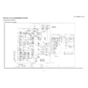
3) Refer to attached sheet SYSTEM Block diagram.
4) Attention: The terminal of IC3303 (VCT) cannot be actually checked by hiding oneself, and check it with another terminal of the same line,
4) Attention: The terminal of IC3303 (VCT) cannot be actually checked by hiding oneself, and check it with another terminal of the same line,
please.
Is IF5V supplied to pin (3) of TUNER (TU1102)?
YES
Check the soldering of TUNER (TU1102), confirm I2C-LINE or
exchange it.
exchange it.
NO
Is D5V output from pin (3) of IC9608 (D5V-REG)?
YES
Check the soldering of Q1105 and TUNER (TU1102).
NO
Is UR12.5V supplied to pin (2) of IC9608 (REG)?
NO
Check the pin (1) (2) of connector PD (P9601).
YES
Check whether D_POW “H” signal is input to pin (7) of IC9608?
YES
Check soldering IC9608 (D5V-REG) or exchange it.
NO
Check whether PS-ON “H” signal is input to pin (2) of IC3305?
YES
Check soldering IC3305 (V-DET) or exchange it.
NO
Check whether PS-ON “H” signal is outputted from pin (AC11) of
IC3303.
IC3303.
LC-32DH57E-BK/RU-BK/S-BK
4 – 3
Power supply (troubleshooting): A power supply does not come to each main circuit/IC. (2)
The power supply of a VIDEO system does not operate.
(IC3303)
(BU3.3V), (D3.3V), (D1.1V), (CPU1.2V)
Checklist
1) The check of the front page POW-UNIT is completed.
••• UR12.5V is output to PD (P9601) (MAIN-UNIT).
(If UR12.5V is not output, confirm the POW-UNIT again and repair.)
2) Check that STB3.3V is supplied to pin (V24) of IC3303 (included MICON), and the PS_ON signal “H” is output from (AC11) pin within a MAIN
UNIT.
(If STB3.3V is not supplied, check IC9605 (BU3.3V-REG), IC9607 (V-DET), and a peripheral circuit.)
(If STB3.3V is not supplied, check IC9605 (BU3.3V-REG), IC9607 (V-DET), and a peripheral circuit.)
3) Refer to attached sheet SYSTEM Block diagram.
4) Attention: The terminal of IC3303 (VCT) cannot be actually checked by hiding oneself, and check it with another terminal of the same line,
4) Attention: The terminal of IC3303 (VCT) cannot be actually checked by hiding oneself, and check it with another terminal of the same line,
please.
Is BU3.3V supplied to pin (V24) of IC3303 (VCT)?
NO
Check whether BU3.3V is outputted from pin (3) of IC9605
(REG).
(REG).
YES
NO
Check whether the voltage detection signal input from IC9607 (V-
DET) (1) pin to IC9605 (7) pinis.
DET) (1) pin to IC9605 (7) pinis.
Is D3.3V, D1.1V, and CPU1.2V supplied to pin (F18) (C6) (K12)
of IC3303 (VCT).
of IC3303 (VCT).
NO
Are D3.3V, D1.1V, and CPU1.2V output from IC9602 (SW) (1)
pin, IC9604 (REG) (3) pin, and IC9603 (REG) (5) pin?
pin, IC9604 (REG) (3) pin, and IC9603 (REG) (5) pin?
YES
NO
Check soldering and the peripheral circuit of IC3303 (VCT).
Or please exchange IC3303.
Or please exchange IC3303.
Check whether the D_1.1V signal inputs to IC9602 (SW) (3) pin
and D_POW signal inputs to IC9604 (REG) (7) pin or check sol-
dering etc.
and D_POW signal inputs to IC9604 (REG) (7) pin or check sol-
dering etc.
Power supply (troubleshooting): A power supply does not come to each main circuit/IC. (3)
The power supply of a AUDIO system does not operate.
(IC1302/IC2701)
(AMP12.5V, S9V, D3.3V)
Checklist
1) The check of the front page POW-UNIT is completed.
••• UR12.5V is output to PD (P9601) (MAIN-UNIT).
(If UR12.5V is not output, confirm the POW-UNIT again and repair.)
2) Check that STB3.3V is supplied to pin (V24) of IC3303 (included MICON), and the PS_ON signal “H” is output from (AC11) pin within a MAIN
UNIT.
(If STB3.3V is not supplied, check IC9605 (BU3.3V-REG), IC9607 (V-DET), and a peripheral circuit.)
(If STB3.3V is not supplied, check IC9605 (BU3.3V-REG), IC9607 (V-DET), and a peripheral circuit.)
3) Refer to attached sheet SYSTEM Block diagram.
4) Attention: The terminal of IC3303 (VCT) cannot be actually checked by hiding oneself, and check it with another terminal of the same line,
4) Attention: The terminal of IC3303 (VCT) cannot be actually checked by hiding oneself, and check it with another terminal of the same line,
please.
Is AMP12.5V supplied to pin (1) (10) of IC2701 (A-AMP)?
NO
Is S12.5V input to pin (3) (4) of PD connector (P9601)?
YES
NO
Check a soldering or contact of a PD connector (P9601).
Is D3.3V supplied to pin (3) of IC1302 (A-SW), and is S9V sup-
plied to pin (10)?
plied to pin (10)?
NO
Check whether D3.3V is outputted from pin (1) of IC9602 (SW),
and S9V is outputted from pin (5) of IC9610 (REG).
and S9V is outputted from pin (5) of IC9610 (REG).
NO
Check whetherD1.1V_ON signal is inputted to pin (3) of IC9602
(SW) and pin (3) of IC9610 (REG).
(SW) and pin (3) of IC9610 (REG).
LC-32DH57E-BK/RU-BK/S-BK
4 – 4
Power supply (troubleshooting): A power supply does not come to each main circuit/IC. (4)
The power supply of a PANEL system does not operate.
(Q9606) (LCD12V)
Checklist
1) The check of the front page POW-UNIT is completed.
••• UR12.5V is output to PD (P9601) (MAIN-UNIT).
(If UR12.5V is not output, confirm the POW-UNIT again and repair.)
2) Check that STB3.3V is supplied to pin (V24) of IC3303 (included MICON), and the PS_ON signal “H” is output from (AC11) pin within a MAIN
UNIT.
(If STB3.3V is not supplied, check IC9605 (BU3.3V-REG), IC9607 (V-DET), and a peripheral circuit.)
(If STB3.3V is not supplied, check IC9605 (BU3.3V-REG), IC9607 (V-DET), and a peripheral circuit.)
3) Refer to attached sheet SYSTEM Block diagram.
4) Attention: The terminal of IC3303 (VCT) cannot be actually checked by hiding oneself, and check it with another terminal of the same line,
4) Attention: The terminal of IC3303 (VCT) cannot be actually checked by hiding oneself, and check it with another terminal of the same line,
please.
YES
Is LCD12V supplied to pin (12)-(15) of LP connector (P2604)?
YES
Replace LCD-CONT-UNIT.
NO
Is LCD12V output from pin (8) of Q9606 (SW)?
YES
Check the surrounding of LP connector (P2604).
NO
Is UR12.5V input to pin (1) of Q9606 (SW)?
NO
Check whether UR12.5V is input to pin (1) (2) of PD connector
(P9601).
(P9601).
YES
Is PNL_POW “H” input to pin (4) of Q9606 (SW)?
NO
Check whether PNL_POW signal outputs “H” from pin (A12) of
IC3303.
IC3303.
YES
Replace Q9606 (SW).

