Sharp LC-30HV4E (serv.man35) User Manual / Operation Manual ▷ View online
5
Setting the System in place
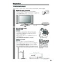
Handling the Display
CAUTION
• The Display is very heavy. Move it with two or more people.
• Do not remove the stand from the Display unless using an
optional bracket to mount it.
• When moving, put your hands on the Display, but never on the
Display speakers.
• Keep enough space above and behind the Display.
Handling the AVC System
CAUTION
• Do not put a VCR or other device on the AVC System.
• Keep enough space above and on the sides of the AVC System.
• Do not block the ventilation openings on the top and left side,
and the exhaust fan on the right side.
• Do not spread a thick cloth beneath the AVC System, or cover it
with one, as this can cause overheating and result in malfunction.
Preparation
Where to place the System
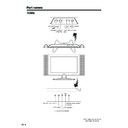
“System” means the Display and AVC System. First select the location where to place the System.
1
2
Selecting the location of the System
• Select a place with no direct sunlight and good ventilation.
• The Display and the AVC System are connected by the system cable.
(See page 6 for details.)
5 cm or more
5 cm or more
on both sides
on both sides
CAUTION
Adjust the screen with both
hands. Put one hand on the
Display and tilt the screen
while steadying the stand
with your other hand.
You can adjust the screen
vertically up to 10 degrees
forward or 8 degrees back-
ward, or rotate 10 degrees
horizontally.
hands. Put one hand on the
Display and tilt the screen
while steadying the stand
with your other hand.
You can adjust the screen
vertically up to 10 degrees
forward or 8 degrees back-
ward, or rotate 10 degrees
horizontally.
5 cm or more
10 cm
or more
Keep enough space
System cable
AVC System
Display
There is an exhaust fan
on the right side.
on the right side.
6
AC INPUT
110V–240V
DISPLAY INPUT2
DISPLAY INPUT1
System cable
AVC System (rear view)
AC cord
Display (rear view)
AC cord
System cable
(GREY)
Connect the plug firmly
until the hooks on both
sides click.
(WHITE)
Connect the plug into the
terminal and secure it by
tightening the thumb screws.
Connect the plug into the
terminal and secure it by
tightening the thumb screws.
(GREY)
(WHITE)
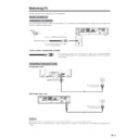
Setting the System
After putting the Display and the AVC System in place, connect the system cables and AC cords. Use the
cable clamp for bundling the cables.
Preparation
Press down the two
upper hooks to remove
the cover toward you.
upper hooks to remove
the cover toward you.
Connecting the system cable and the AC cord to the Display
1
2
3
Removing the terminal cover
Connecting the system cable and the AC cord to the AVC System
CAUTION
• TO PREVENT RISK OF ELECTRIC SHOCK, DO NOT TOUCH UN-INSULATED PARTS OF ANY CABLES WITH THE
AC CORD CONNECTED.
7
Preparation
4
5
6
Attaching the clamp to the leg of the Display
Bundling the cables with the clamp
Closing the terminal cover
Display (rear view)
Cables come out from
the small opening.
the small opening.
8
Preparation
Setting the Display on the wall
Setting the AVC System with the stand
CAUTION
• Installing the LCD Colour TV requires special skill that should only be performed by qualified service personnel.
Customers should not attempt to do the work themselves. SHARP bears no responsibility for improper mounting or
mounting that results in accident or injury.
mounting that results in accident or injury.
1
Using an optional bracket to mount the Display
• You can ask a qualified service personnel about using an optional AN-37AG1 bracket to mount the Display
• You can ask a qualified service personnel about using an optional AN-37AG1 bracket to mount the Display
to the wall.
• Carefully read the instructions that come with the bracket before beginning work.
Vertical mounting
Angular mounting
Hanging on the wall
AN-37AG1 wall mount bracket. (See the bracket instructions for details.)
How to install the AVC System vertically using the stand unit.
• Use the supplied stand unit for installing the AVC System vertically in an upright position.
• Use the supplied stand unit for installing the AVC System vertically in an upright position.
Stick each spacer to the
stand as shown.
stand as shown.
Peel each spacer
away from the
paper and attach
to the four bulging
areas on the stand.
away from the
paper and attach
to the four bulging
areas on the stand.
2
Attach each cushion to
the stand as shown.
the stand as shown.
3
Fit the stand to the AVC
System.
System.
Peel each cushion
away from the
paper and attach
to the four areas at
the bottom.
away from the
paper and attach
to the four areas at
the bottom.
Insert the stand into the AVC
System, making sure that the
thick and thin bulges of the
stand align with the big and
small holes on the AVC
System.
System, making sure that the
thick and thin bulges of the
stand align with the big and
small holes on the AVC
System.
Stand
spacer
spacer
Bulge
Stand cushion
Thin bulge
Thick
bulge
bulge
Big hole
Small
hole
hole
4
Attach the stand using the
stand screws as shown.
stand screws as shown.
Stand screw
The AVC System installed
vertically with the stand.
vertically with the stand.
NOTE
• When mounting the AVC System vertically, always use the supplied stand. Be careful not to block vent holes when
standing up directly on the floor or a flat surface as this can result in equipment failure.
Attaching point
Attaching point
Bulge
Display

