Sharp LC-26D44E (serv.man5) Service Manual ▷ View online
LC-26D44E/S/RU-BK/GY
4 – 1
LC26D44E-BK
Service Manual
CHAPTER 4.
TROUBLE SHOOTING TABLE
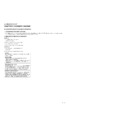
[1] TROUBLE SHOOTING TABLE
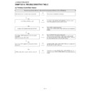
No power supply (Front LED does not light up) and no power-up even if turned on (Front LED light up).
Is the wire harness in the unit properly connected?
NO
Reconnect and recheck the wire harness.
YES
Are F7100 and F7101 normal?
NO
Are L7100, L7102, VAR7100, X7100, BD7100, T7100, etc. faulty?
Check if the peripheral circuits are short-circuited.
Check if the peripheral circuits are short-circuited.
YES
Is approx. 400V applied to both ends of C7100?
NO
Does the PFC circuit normally work?
(Check L7103, T7100, D7100, U7300, Q7305, etc. and the peripheral
circuits.)
(Check L7103, T7100, D7100, U7300, Q7305, etc. and the peripheral
circuits.)
YES
Is a voltage of BU5V applied to pin (11) of connector
(CN7200)?
(Set the main power SW to OFF.)
(CN7200)?
(Set the main power SW to OFF.)
NO
Does the SWITCHING circuit normally work?
(Check the primary side of T7101, U7101, Q7101, D7105, D7107,
etc., the secondary side of D7290, L7290, Q7291, U7291, F7290, etc.
and the peripheral circuits such as AC_DET circuit.)
(Check the primary side of T7101, U7101, Q7101, D7105, D7107,
etc., the secondary side of D7290, L7290, Q7291, U7291, F7290, etc.
and the peripheral circuits such as AC_DET circuit.)
YES
Are 13V and S13V supplied when the power switch is
turned on?
turned on?
NO
Do D7260, Q7265, U7265, L7260, F7250, F7260, etc. normally work?
(PS_ON_LINE, AC_DET_LINE, etc.)
(PS_ON_LINE, AC_DET_LINE, etc.)
YES
Is 38V supplied when the power switch is turned on?
NO
Check the primary side of D7250, D7251, L7250, ZD7250, etc., the
protection circuits of Q7250, ZD7250, ZD7251, etc. and the peripheral
circuits.
protection circuits of Q7250, ZD7250, ZD7251, etc. and the peripheral
circuits.
LC-26D44E/S/RU-BK/GY
4 – 2
The backlight does not light
Are all fluorescent lamps on?
NO
Check each fluorescent lamp, and replace if defective.
(CN7501-9, etc.)
(CN7501-9, etc.)
NO
Is 38V applied to both ends of C7500/C7501?
NO
Refer to "No power supply (Front LED does not light up)" and "No
power-up even if turned on (Front LED light up)".
power-up even if turned on (Front LED light up)".
YES
Is F7500 normal?
NO
Check if the peripheral circuits are short-circuited or parts are faulty.
(L7500, MOS7500-3, etc.)
(L7500, MOS7500-3, etc.)
YES
Is IC12V supplied from the collector side of Q7501?
NO
Check if the STB_ON/OFF signal sent from PIN(2) of connector
CN7502. (Q7501-2, Q7508, Q7510, etc.)
CN7502. (Q7501-2, Q7508, Q7510, etc.)
YES
Is a voltage of 5V applied to PIN(5) of IC7500?
NO
Does the regulator circuit normally work?
(Check Q7503, U7500, etc. and the peripheral circuits.)
(Check Q7503, U7500, etc. and the peripheral circuits.)
YES
Does each control signal of connector CN7502 normally
function?
function?
NO
Check each control circuit.
PIN(3) OFL1 (PWM light control signal input)
OFL (PWM light control signal input)/H: Lamp ON, L: Lamp OFF
PIN(5) ERR (Error output)
ERR (Error output)/H: Normal, L: Error
PIN(7) REG2 (Light control method identification)
REG2 Light control method identification)/H: External PWM input, L:
Analog voltage input
Analog voltage input
YES
Is [0] displayed as the number of [LAMP_ERROR] in the
process mode?
process mode?
NO
Reset the number of [LAMP_ERROR] to the default value in the pro-
cess mode?
cess mode?
YES
Is the drive signal sent from PIN(19, 20)/(PDRV_A,
NDRV_B and PIN(12, 11)/ (RDR_C, NDRV_D) of IC7500?
NDRV_B and PIN(12, 11)/ (RDR_C, NDRV_D) of IC7500?
NO
Check IC7500 and the peripheral circuits.
YES
Does the drive output circuit normally work?
NO
Check MOS7500-3, etc. and the peripheral circuits.
YES
Does the secondary side of T7500-4 normally work?
NO
Check T7500-4, D7523-7, etc. and the peripheral circuits.
YES
Check the feedback circuits such as FB_LINE,
FBK_LINE, FB_1_LINE, OVP_LINE.
FBK_LINE, FB_1_LINE, OVP_LINE.
LC-26D44E/S/RU-BK/GY
4 – 3
The sound is not emitted from the speaker though the picture has come out.
No sound output in all modes.?
Is the audio signal output of pins (28/L) and (27/R) of
IC3001 (MAIN_MICON) normal?
IC3001 (MAIN_MICON) normal?
NO
Check IC3001 and its peripheral circuits.
YES
Is audio signal input to pin(5/L), pin(9/R) of IC2701(AMP)?
NO
Check the line between IC3001 and IC2701.
YES
Is MUTE circuit [MUTE_SP_LINE, RESET_N_LINE] nor-
mal?
mal?
NO
Check the MUTE_SP_LINE and RESET_N_LINE.
(Q2701, etc.)
(Q2701, etc.)
YES
Is the audio signal output of pins (3, 4) (L-ch) and (2, 1)
(R-ch) of P2701(AOUDIO-CONNECTOR) normal?
(R-ch) of P2701(AOUDIO-CONNECTOR) normal?
NO
Check IC2701 and its peripheral circuits.
YES
Check Speaker (right and left) and wire harness.
No sound (during the reception of TV(ANALOG) broadcasting)
Does not the sound go out though the picture has come out when UHF/VHF is received?
Is the SIF signal output from pin (4) of TUNER (TU201)?
NO
Check the tuner and its peripheral circuits.
Replace as required.
Replace as required.
YES
Is the SIF signal sent to pins (31) of IC3001
(MAIN_MICON)?
(MAIN_MICON)?
NO
Check the line between TU201 and IC3001.
YES
Refer to “No sound output in all modes”.
LC-26D44E/S/RU-BK/GY
4 – 4
No sound (during the reception of TV(DIGITAL) broadcasting)
Does not the sound go out though the picture has come out when DTV is received?
Is the audio signal output from PIN(24,25)/ LETFT_M/P,
PIN(28,29)/ RIGH_M/P of IC4001(SET-
TOP_BOX_DECODER).
PIN(28,29)/ RIGH_M/P of IC4001(SET-
TOP_BOX_DECODER).
NO
Check IC4001 and its peripheral circuits.
YES
Is the audio signal input to PIN(6,5)/ LETFT_M/P, (2,3)/
RIGH_M/P of IC4005(OP-AMP)?
RIGH_M/P of IC4005(OP-AMP)?
NO
Check the line between IC4001 and IC4005.
YES
Is the audio signal sent from PIN(7)/ AIN1L, (1)/AIN1R of
IC4005 to PIN(10), PIN(9) of IC3001 (MAIN_MICON)?
IC4005 to PIN(10), PIN(9) of IC3001 (MAIN_MICON)?
NO
Check the line between IC4005 and IC3001.
YES
Refer to “No sound output in all modes”.
No sound from external input devices (1)
Does not the sound of the audio signal input to EXT1(SCART1) go out?
Does not the sound of the audio signal input to EXT2(SCART2) go out?
Does not the sound of the audio signal input to EXT2(SCART2) go out?
EXT1
Is the audio signal properly sent to pins (6) (AIN3_L) and
(2) (AIN3_R) of SCART1(SC1102)?
Is the audio signal properly sent to pins (6) (AIN3_L) and
(2) (AIN3_R) of SCART1(SC1102)?
NO
Check the setting of an external input device that connects of
SC1102.
SC1102.
EXT2
Is the audio signal properly sent to pins (6) (AIN2_L) and
(2) (AIN2_R) of SCART2(SC1101)?
Is the audio signal properly sent to pins (6) (AIN2_L) and
(2) (AIN2_R) of SCART2(SC1101)?
NO
Check the setting of an external input device that connects of
SC1101.
SC1101.
YES
EXT1
Is the audio signal properly sent to pins (14) (AIN3_L) and
(13) (AIN3_R) of IC3001(MAIN_MICON)?
Is the audio signal properly sent to pins (14) (AIN3_L) and
(13) (AIN3_R) of IC3001(MAIN_MICON)?
NO
Check the line between SC1102 and IC3001.
EXT2
Is the audio signal properly sent to pins (12) (AIN2_L) and
(11) (AIN2_R) of IC3001(MAIN_MICON)?
Is the audio signal properly sent to pins (12) (AIN2_L) and
(11) (AIN2_R) of IC3001(MAIN_MICON)?
NO
Check the line between SC1101 and IC3001.
YES
Refer to “No sound output in all modes”.

