Sharp LC-20SD4E Service Manual ▷ View online
B1-1
DISASSEMBLY INSTRUCTIONS
1. REMOVAL OF MECHANICAL PARTS
AND P.C. BOARDS
1-1:
1.
2.
3.
4.
5.
2.
3.
4.
5.
Remove the 1 screw
1
.
Remove the Stand Cover in the direction of arrow (A).
Remove the 4 screws
Remove the 4 screws
2
.
Remove the Stand Ass'y in the direction of arrow (B).
Remove the Dammy Card in the direction of arrow (C).
Remove the Dammy Card in the direction of arrow (C).
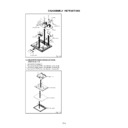
1-2: BACK CABINET (Refer to Fig. 1-2)
1.
2.
2.
Remove the 9 screws
1
.
Remove the Back Cabinet in the direction of arrow.
STAND COVER/STAND ASS'Y/DAMMY CARD
(Refer to Fig. 1-1)
(Refer to Fig. 1-1)
Stand Ass'y
1
Fig. 1-1
Stand Cover
2
2
2
2
Dammy Card
(A)
(B)
Fig. 1-2
1
Back Cabinet
1
1
1
1
1
1
1
1-3: ANGEL EARTH-1/DIGITAL PCB (Refer to Fig. 1-3)
1.
2.
3.
3.
Disconnect the following connectors:
(CD003 and CP505).
Remove the 7 screws
(CD003 and CP505).
Remove the 7 screws
1
.
Remove the Angel Earth-1 and Digital PCB in the
direction of arrow.
direction of arrow.
Fig. 1-3
1
Angel Earth-1
1
1
1
1
Digital PCB
1-4: PCB ASS'Y (Refer to Fig. 1-4)
1.
2.
3.
4.
2.
3.
4.
5.
6.
7.
6.
7.
8.
9.
10.
9.
10.
11.
12.
13.
14.
15.
13.
14.
15.
Disconnect the following connector: (CP202).
Remove the 3 screws
Remove the 3 screws
1
.
Remove the Operation PCB in the direction of arrow (A).
Disconnect the following connectors:
(CP3201, CP801 and CP802).
Remove the 4 screws
Disconnect the following connectors:
(CP3201, CP801 and CP802).
Remove the 4 screws
2
.
Remove the Scaler PCB in the direction of arrow (B).
Disconnect the following connectors:
(CP503, CP302, CP303, CP6700, CP6701, CP6702,
CP6703 and CP6704).
Remove the 7 screw
Disconnect the following connectors:
(CP503, CP302, CP303, CP6700, CP6701, CP6702,
CP6703 and CP6704).
Remove the 7 screw
3
.
Remove the 9 screws
4
.
Remove the AV PCB and Back Light PCB in the
direction of arrow (C).
Disconnect the following connectors:
(CP503 and CP2201).
Remove the 2 screw
direction of arrow (C).
Disconnect the following connectors:
(CP503 and CP2201).
Remove the 2 screw
5
.
Remove the Remocon PCB in the direction of arrow (D).
Remove the Holder PCB Tuner.
Remove the Tuner PCB in the direction of arrow (E).
Remove the Holder PCB Tuner.
Remove the Tuner PCB in the direction of arrow (E).
(C)
1
1
1

