Sharp LC-20M4E (serv.man4) Service Manual ▷ View online
18
LC-20M4E
A
B
C
D
E
F
G
H
I
J
1
2
3
4
5
6
7
8
9
10
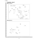
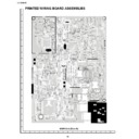
CHASSIS LAYOUT
MAIN Unit (Side-A)
MAIN Unit (Side-B)
19
LC-20M4E
A
B
C
D
E
F
G
H
I
J
1
2
3
4
5
6
7
8
9
10
JACK Unit
INVERTER Unit
SWITCH Unit
1
2
3
4
5
6
7
8
9
10
11
12
13
14
15
16
17
18
19
20
A
B
C
D
E
F
G
H
I
J
LC-20M4E
LC-20M4E
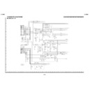
BLOCK DIAGRAM
VIDEO IN
AUDIO L/R IN
PY IN
AV1
IN
POWER IN
DC 13V
DC 13V
VIDEO IN/OUT
AUDIO L/R
J4401
J4303
J4403
PB IN
J4404
J4404
PR IN
J4405
J4405
IN/OUT
AV2
IN/OUT
J4402
J4302
MSP
MUTE
MUTE
VPC
BUFFER
IN/OUT
SELECTOR
IC351
SELECTOR
IC351
IC902
IC901
HEAD PHONE
J4001
J4001
J4701
LPF
L/R
AUDIO AMP
REVERSE
FRONT SP
REAR SP
AUDIO AMP
AUDIO AMP
FRONT SP
FRONT SP
REAR SP
PY.PB.PR
AV1
VIDEO SELECTOR
IC402
I2C
LCD
CONTROLLER
IC1201
CONTROLLER
IC1201
FIFO
IC1202
IC1202
Y/C
CLOCK.H/VSYNC.FIELD
LCD
PANEL
R.G.B CONTROL SIGNAL
IC1102
IC1103
IC1104
IC1105
IC1106
IC1107
IC1108
IC1103
IC1104
IC1105
IC1106
IC1107
IC1108
IC1109
IC1110
GRADUATION
POWER FOR
LCD
POWER FOR
LCD
COMMON
DAC
IC1101
MPU
IC2001
I2C
CONTROL SIGNAL
SYNC
SEPARATION
SEPARATION
VOUT
IC801
SYNC
75ohm
BUFFER
Q453
Q454
Q454
AGND
IN/OUT
E2PROM
IC2004
IC2004
RESET
IC2002
IC2002
5V Reg
IC2701
IC2701
5V
IC701
PWM
DC/DC
TRANS
T701
5V
38V
16V
9V
-8V
3.3V Reg
IC781
IC781
3.3V
29V
8V
Q704
Q7306
IC702
LAMP
DC/AC
TRANS
TRANS
INVERTER
DRIVE
TR
DRIVE
TR
LAMP
CHECK
CHECK
LAMP GND
DC12V
R/C
RECEIVER
CONTROL
KEY
KEY
BRIGHTNESS
PULS
IC903
IC302
IC301
IC303
IC401
SW PWB
JACK PWB
MAIN PWB
LCD UNIT
I2C
YC IN
SC4401
SC4401
SSW
SSW
SC
SY
SY
SC
INV PWB
DC12V
CONTROL SIGNAL
RELAY RY351
PWB GND
PANEL SHELD
PWB GND
PANEL SHELD
PWB GND
PANEL SHELD
PWB GND
PANEL SHELD
GASKET
QEARZ0017CEZZ
WIRE
QCNW-A272WJZZ
QCNW-A272WJZZ
QCNW-
A268WJZZ
QCNW-
A269WJZZ
FFC
FFC
WIRE
QCNW-
WIRE
QCNW-A271WJZZ
WIRE
QCNW-5372CEZZ
QCNW-5372CEZZ
FFC
QCNW-
A270WJZZ
A270WJZZ
A271WJZZ
SCREW
SCREW
RCORF
A005WJZZ
Q1702
Q1703
Q1704
Q1705
Q1703
Q1704
Q1705
T1701
T1702
T1703
T1704
T1705
T1706
T1702
T1703
T1704
T1705
T1706
20~21
22
LC-20M4E
DESCRIPTION OF SCHEMATIC DIAGRAM
1. When the exclusive-use AC adapter is used, the
colour bar signal of colour bar generator for service
is input to get the normal screen. When the audio is
minimized, the voltage value is measured with the
20 k
is input to get the normal screen. When the audio is
minimized, the voltage value is measured with the
20 k
Ω
/V tester.
2. When the exclusive-use AC adapter is used, the
colour density, lightness and colour hue are set to
the center position, and the signal of colour bar
generator for service is observed to get waveform.
The wave form test point is indicated with the mark
(
the center position, and the signal of colour bar
generator for service is observed to get waveform.
The wave form test point is indicated with the mark
(
) in the wiring diagram.
3. Indication of resistors and capacitors
[Resistors]
Unit
: Nonindication …
Ω
, K…k
Ω
,
M … M
Ω
Error : Nonindication …
±
5%
F …
±
1%
D …
±
0.5%
[Capacitor]
Unit
: Nonindication or
µ
…
µ
F,
P or p … pF
IMPORTANT SAFETY NOTICE:
PA RT S M A R K E D W I T H "
PA RT S M A R K E D W I T H "
å
" (
)
A R E
INPORTANT FOR MAINTAINING THE SAFETY OF
THE SET.
BE SURE TO REPLACE THESE PARTS WITH
SPECIFIED ONES FORMAINTAINING THE SAFETY
AND PERFORMANCE OF THE SET.
THE SET.
BE SURE TO REPLACE THESE PARTS WITH
SPECIFIED ONES FORMAINTAINING THE SAFETY
AND PERFORMANCE OF THE SET.
CAUTION:
This circuit diagram is original one, therefore there
may be a slight difference from yours.
This circuit diagram is original one, therefore there
may be a slight difference from yours.
Resistors
Nonindication
Carbon-film resistor
C
Solid resistor
S
Metal-oxide-film resistor
N
Metal-film resistor
W
Cement resistor
T
Special resistor
Capacitors
Nonndication
Ceramic capacitor
ML
Mylar capacitor
PF
Polypropylene
film capacitor
TA
Tantalum capacitor
ST
Styrol capacitor
[Item]
Display

