Sharp LC-20B5E (serv.man6) Service Manual ▷ View online
8
LC-20B5E
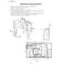
REMOVING OF MAJOR PARTS
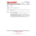
1. Remove the four lock screws from the stand, and detach the stand.
2. Remove the terminal covers (large and small).
3. Remove the three terminal screws.
4. Remove the fourteen lock screws from the cabinet B.
5. With the card eject button held down, open the cabinet in order of
5-1
thru
5-6
, and detach
the cabinet B by sliding it toward the PC card slot.
6. Remove the four lock screws from the stand angle, and detach the reinforcement angle.
7. Remove the wire holder and tape, and disconnect the connecting cable.
8. Disconnect all the connectors from all the PWBs.
Cabinet B
4
3
1
2
2
5
5-6
PC Card slot
Cabinet A
Terminal Cover (S)
Terminal Cover (L)
Stand
5-4
5-3
5-2
5-1
5-5
P4050
CN2
SC1202
P701
P2003
SC1201
SC3403
P6704
P6703
P6702
P6701
P6700
P6706
P3302
P3404
P3704
P3303
P4001
P3703
P3201
SC1204
SC2001
P5003
CN3
P2005
P9201
P1601
P2006
Operation PWB
Reinforcement Angle
Main PWB
R/C, LED PWB
Wire Holder
Inverter PWB
Card LED PWB
Tape
6
8
8
8
8
8
8
8
8
8
8
7
7
Analog PWB
9
LC-20B5E
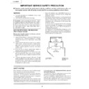
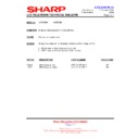
9. Remove the two lock screws from the operation panel (top cover), and detach the operation panel (top cover).
10. Remove the two lock screws from the operation PWB, and detach the operation PWB.
11. Remove the lock screw from the shield, and detach the shield from the main PWB.
12. Remove the two lock screws from the R/C, LED PWB, and detach the R/C, LED PWB.
13. Remove the two lock screws each from the speaker boxes (left and right), and detach both the speaker boxes.
Speaker Box (R)
R/C, LED PWB
Analog PWB
Main PWB
Speaker Box (L)
Inverter PWB
Shield
Operation Panel (Top Cover)
Operation
PWB
PWB
13
10
11
9
13
12
10
LC-20B5E
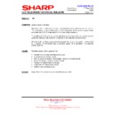
14. Remove the two lock screws from the inverter PWB, and detach the inverter PWB.
15. Remove the five lock screws from the main PWB, and undo the claws a and b. Detach the main PWB by lifting
15. Remove the five lock screws from the main PWB, and undo the claws a and b. Detach the main PWB by lifting
the area around the claws and pulling the PWB out.
16. Remove the one lock screw from the card frame cover over, and detach the card frame cover.
17. Remove the two lock screws from the 21-pin terminal.
18. Remove the four lock screws from the analog PWB, and undo the claws c and d. Detach the chassis frame (right)
17. Remove the two lock screws from the 21-pin terminal.
18. Remove the four lock screws from the analog PWB, and undo the claws c and d. Detach the chassis frame (right)
from the analog PWB by pulling out the terminals. In the same way, undo the claws e and f, and detach the
chassis frame (left) from the analog PWB by pulling out the terminals.
chassis frame (left) from the analog PWB by pulling out the terminals.
Note: When detaching the main PWB and analog PWB, be careful not to break the PWB-fixing claws.
19. Remove the one lock screw from the card LED PWB, and detach the card LED PWB.
19. Remove the one lock screw from the card LED PWB, and detach the card LED PWB.
Inverter PWB
Main PWB
Analog PWB
f
Chassis Frame (L)
Chassis Frame (R)
Card Frame Cover
Card LED PWB
15
15
18
19
14
17
16
e
a
b
c
d
11
LC-20B5E
»
Precautions in handling the liquid crystal panel
1. Handle it in a clean room. (above 50% humidity)
2. The worker must wear an earth band.
3. Be careful not to drop, vibrate and shock the panel.
4. Use an ionizer. (within 30 cm)
1. Handle it in a clean room. (above 50% humidity)
2. The worker must wear an earth band.
3. Be careful not to drop, vibrate and shock the panel.
4. Use an ionizer. (within 30 cm)
20. Remove the three lock screws from the liquid crystal panel, and detach the liquid crystal panel unit.
21. Remove the reflecting/polarizing sheet, prism sheet, diffusion sheet and diffusion plate.
22. Remove the lamp holder (top)-A, -B and the lamp holder (bottom) from the lamp unit assembly.
23. Remove the upper and lower reflection sheets from the back shield.
21. Remove the reflecting/polarizing sheet, prism sheet, diffusion sheet and diffusion plate.
22. Remove the lamp holder (top)-A, -B and the lamp holder (bottom) from the lamp unit assembly.
23. Remove the upper and lower reflection sheets from the back shield.
Reflection Sheet (Top)
(PSHEPA103WJZZ)
(PSHEPA103WJZZ)
Lamp Holder (Top)-B
(LHLDZA212WJKZ)
(LHLDZA212WJKZ)
Lamp Unit Ass'y
(CLMP-A024WJ01)
(CLMP-A024WJ01)
Reflection Sheet (Bottom)
(PSHEPA104WJZZ)
(PSHEPA104WJZZ)
Lamp Holder (Bottom)
(LHLDZA213WJKZ)
(LHLDZA213WJKZ)
Back Shield
(PSLDMA312WJFW)
(PSLDMA312WJFW)
Lamp Holder (Top)-A
(LHLDZA211WJKZ)
(LHLDZA211WJKZ)
Diffusion Sheet
(PSHEPA127WJZZ)
(PSHEPA127WJZZ)
Reflection/Defelction Sheet
(PSHEPA101WJZZ)
(PSHEPA101WJZZ)
Diffusion Plate
(PCOVUA014WJZZ)
(PCOVUA014WJZZ)
Prism Sheet
(PSHEPA163WJZZ)
(PSHEPA163WJZZ)
20" LCD Panel Unit
20
23
22
21
Display

