Sharp LC-20B4E (serv.man6) Service Manual ▷ View online
8
LC-20B4E
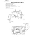
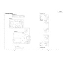
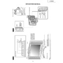
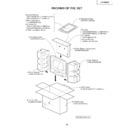
REMOVING OF MAJOR PARTS
1. Remove the stand fixing screws (4 pcs.).
2. Remove the two terminal covers.
3. Remove the terminal section fixing screws (2 pcs.).
4. Remove the cabinet B fixing screws (12 pcs.).
5. Remove the cabinet B after opening from the direction of an arrow.
6. Peel off the tape. Remove the reinforcement angle fixing screws (4 pcs.).
7. Peel off the tape.
8. Detach the connector from each PWB.
VO
L
CH
ME
NU
TV
/V
ID
EO
MA
IN
P
OW
ER
Cabinet A
Cabinet B
Stand
Terminal Cover (S)
Terminal Cover (L)
1
4
2
3
5
5
4
2
4
Tuner PWB
Tape
Inverter-A
PWB
PWB
Inverter-B PWB
Main PWB
R/C, LED PWB
Operation PWB
7
6
6
Reinforcement Angle
8
8
8
8
Tape
8
8
8
8
8
8
8
8
8
8
8
8
8
8
8
8
8
P4004
P3601 P3602
P3302
P3303
P1902
P701
P2001
P6705
P4001
SC1204
SC2002
SC1202
SC1203
SC3902
P3304
P3301
P3902
P6706
9
LC-20B4E
9. Remove the inverter-A PWB fixing screws (2 pcs.).
10.Remove the inverter-B PWB fixing screws (1 pc.).
11.Remove the main PWB fixing screws (3 pcs.).
12.Remove the 21-pin terminal fixing screw (2 pcs.).
13.Remove the tuner PWB fixing screws (3 pcs.) and detach the chassis frame cover fixing hooks.
14.Remove the R/C, LED PWB fixing screws (2 pcs.).
15.Remove the operation PWB fixing screws (2 pcs.).
13
9
10
Inverter-A
PWB
PWB
Main PWB
Chassis Frame
Chassis Frame Cover
Tuner
PWB
PWB
Inverter-B
PWB
PWB
Operation PWB
15
14
R/C, LED PWB
11
12
13
13
10
LC-20B4E
»
Precautions in handling the LCD panels
1. Work in a clean room (with humidities below 50%).
2. Be sure to wear an anti-static armband.
3. Handle the panels on an electro-conductive mat.
4. Be careful not to fall, shake and shock the panels.
1. Work in a clean room (with humidities below 50%).
2. Be sure to wear an anti-static armband.
3. Handle the panels on an electro-conductive mat.
4. Be careful not to fall, shake and shock the panels.
16. Remove the LCD panel unit fixing screws (4 pcs.).
17. Remove the ITO earth spring fixing screw (1 pc.).
18. Remove the reflection/deflection, prism, diffusion, ITO sheets and diffusion panel.
19. Remove the lamp fixing holder fixing screws (6 pcs.).
20. Detach the lamp unit-A/B.
21. Remove the reflection mirror fixing screws. (6 pcs.).
17. Remove the ITO earth spring fixing screw (1 pc.).
18. Remove the reflection/deflection, prism, diffusion, ITO sheets and diffusion panel.
19. Remove the lamp fixing holder fixing screws (6 pcs.).
20. Detach the lamp unit-A/B.
21. Remove the reflection mirror fixing screws. (6 pcs.).
21
20
19
17
18
19
16
16
Back shield
(PSLDM4685CEFW)
(PSLDM4685CEFW)
Reflection Mirror
(PMiR-0296CEZZ)
(PMiR-0296CEZZ)
Lamp Fixing Holder
(LHLDZ2176CEZZ)
(LHLDZ2176CEZZ)
Diffusion Panel
(PCOVU0107CEZZ)
(PCOVU0107CEZZ)
ITO Sheet
(PSHEP0289CEZZ)
(PSHEP0289CEZZ)
Prism Sheet
(PSHEP0287CEZZ)
(PSHEP0287CEZZ)
20" LCD Panel Unit
Reflection/Deflection Sheet
(PSHEP0286CEZZ)
(PSHEP0286CEZZ)
Diffusion Sheet
(PSHEP0288CEZZ)
(PSHEP0288CEZZ)
ITO Earth Spring
(MSPRP1220CEFW)
(MSPRP1220CEFW)
Lamp Fixing Holder
(LHLDZ2176CEZZ)
(LHLDZ2176CEZZ)
Lamp Unit-B
(KLMP-0125CEZZ)
(KLMP-0125CEZZ)
Lamp Unit-A
(KLMP-0124CEZZ)
(KLMP-0124CEZZ)
11
LC-20B4E
»
Precautions at the time of the side B(back) service of main unit.
1. Remove only SC2002 of the FFC for connection between Main unit(SC2002) and Tuner unit(SC3902), and con-
1. Remove only SC2002 of the FFC for connection between Main unit(SC2002) and Tuner unit(SC3902), and con-
nect the extended cable (QCNW-A369WJZZ) for service.
2. Peel off the tape.
3. Remove only P701 of the FFC for connection between Main unit(P701) and Tuner unit(P1902), and connect the
3. Remove only P701 of the FFC for connection between Main unit(P701) and Tuner unit(P1902), and connect the
extended cable (QCNW-B194WJZZ) for service.
4. Remove the main unit fixing screws(2 pcs.), a substrate is reversed.
Tuner PWB
Main PWB
Main PWB
(Side B)
(Side B)
1
3
2
4
Tape
SC2002
SC3902
P701
P1902
Step
Part No.
Description
1
QCNW-A369WJZZ
Extension Cable 50-pin Main (SC2002)-Tuner (SC3902)
3
QCNW-B194WJZZ
Extension Cable 12-pin Main (P701)-Tuner (P1902)
Display

