Sharp LC-19D1EWH (serv.man5) Service Manual ▷ View online
LC-19D1E/S-BK/WH
4 – 2
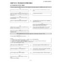
Power supply (troubleshooting): A power supply does not come to each main circuit or IC. (2)
The power supply of a VIDEO system/IC801 (DVP) does not
operate.
Checklist:
1) The check of the front page POW (1) is completed.
• • • UR12V is output to SC1204 (MAIN-PCB).
(If UR12V is not output, confirm the POW(1) again and repair.)
2) Check that BU3.3V is supplied to IC2002 (SUB-MICON), and the AC-CTL signal H is output from 35pin within a MAIN board.
(If BU3.3V is not supplied, check IC2004 (BU3.3V-REG) and a periferal circuit.)
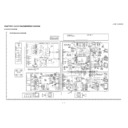
3) Refer to attached sheet Power-Block diagram.
Is B1.5V supplied to pin(D12) of IC801 (DVP) ?
NO
Check whether B1.5V is output from pin(6) of IC705.
YES
NO
Check whether POWER-CTL signal is input to pin(4) of IC705
(REG).
(REG).
YES
Is B12V supplied to pin(5) of IC705 (REG) ?
YES
Exchange IC705 (REG).
Is B3.3V supplied to pin(R19)(D5) of IC801(DVP) ?
NO
Check whether B3.3V is output from pin(3) of IC703 (REG).
YES
NO
Check whether UR 12V-CTL signal is input to pin(7) of
IC703(REG).
IC703(REG).
YES
Is B12V supplied to pin(2) of IC703 (REG) ?
YES
Exchange IC703 (REG).
Is B3.3V supplied to pin(1)(19) of IC9201 (RSDS-TR) ?
NO
Check whether B3.3V is output from pin(3) of IC703 (REG).
YES
NO
Check the soldering of IC801 and IC703 or exchange it.
Check whether UR 12V-CTL signal is input to pin(7) of
IC703(REG).
IC703(REG).
YES
Is B12V supplied to pin(2) of IC703 (REG) ?
YES
Exchange IC703 (REG).
LC-19D1E/S-BK/WH
4 – 3
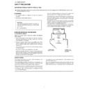
Power supply (troubleshooting): A power supply does not come to each main circuit or IC. (3)
The power supply of a AUDIO system does not operate.
Checklist:
1) The check of the front page POW (1) is completed.
• • • UR12V is output to SC1204 (MAIN-PCB).
(If UR12V is not output, confirm the POW(1) again and repair.)
2) Check that BU3.3V is supplied to IC2002 (SUB-MICON), and the AC-CTL signal H is output from 35pin within a MAIN board.
(If BU3.3V is not supplied, check IC2004 (BU3.3V-REG) and a periferal circuit.)
3) Refer to attached sheet Power-Block diagram.
Is UR12V supplied to pin(47)(46)(39)(38) of IC303(P-AMP) ?
NO
Check the UR12V line from pin (13-15) of SC1204.
YES
Is B3.3V supplied to pin(13)(26) of IC302(A-CODEC) ?
NO
Check the soldering of IC302 or Is B3.3V output from pin(3) of
IC703(REG)?
IC703(REG)?
YES
NO
Is UR12V supplied to pin(7) of IC703(REG) ?
Check the soldering of IC703(REG) or exchange it.
Check the soldering of IC703(REG) or exchange it.
Is B9V supplied to pin(14) of IC301(A-SEL) ?
NO
Is B3.3V output from pin(5) of IC702(REG)?
YES
NO
Check the soldering of IC301(A-SEL) or exchange it.
Check the soldering of IC702(REG) or exchange it
LC-19D1E/S-BK/WH
4 – 4
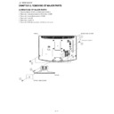
Power supply (troubleshooting): A power supply does not come to each main circuit or IC. (4)
The power supply of a PANEL system does not operate.
Checklist:
1) The check of the front page POW (1) is completed.
• • • UR12V is output to SC1204 (MAIN-PCB).
(If UR12V is not output, confirm the POW(1) again and repair.)
2) Check that BU3.3V is supplied to IC2002 (SUB-MICON), and the AC-CTL signal H is output from 35pin within a MAIN board.
(If BU3.3V is not supplied, check IC2004 (BU3.3V-REG) and a periferal circuit.)
3) Refer to attached sheet Power-Block diagram.
Is B12V output from pin(6) of Q702(SW)?
NO
Check the soldering of Q702(SW) or exchange it.
YES
Is VGL(-7V)/VGH (28V) output from pin(1)/(3) of IC704(SW-
REG)?
REG)?
NO
Check the soldering of Q704(SW-REG) or exchange it.
YES
Is VLSB14.6V output from pin(3) of IC701 (VLSB14.6V-REG)?
NO
Check the soldering of IC701(VLSB12V-REG) or exchange it.
YES
Is VH24/VH56/VL 56/VL24 output from pin(7)/(1)/(8)/ (14) of
IC1001(OP-AMP)?
IC1001(OP-AMP)?
NO
Check the soldering of IC1001(OP-AMP) or exchange it.
YES
Is COM-BIAS output (4.2V) from pin(7) of IC9202(COM-BIAS)?
NO
Check the soldering of IC9202(COM-BIAS) or exchange it.
YES
Is each voltage supplied to SC9201(CONN) ?
(VLSB14.6V,VGH,VGL,COM-BIAS)
(VLSB14.6V,VGH,VGL,COM-BIAS)
NO
Check the soldering of SC9201(CONN) or exchange it.
YES
Check the FPC of PANEL or exchange PANEL-MODULE.
LC-19D1E/S-BK/WH
4 – 5
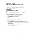
No sound (1) (during the reception of DTV broadcasting)
No audio output during
DTV reception
DTV reception
Checklist :
1) Is the volume set to MIN or MUTE on the remote control ?
1) Is the volume set to MIN or MUTE on the remote control ?
• • • Set the desired volume.
2) Is ANT-CABLE disconnected or connected improperly ?
• • • Connect it correctly as per the operation manual.
(AV-UNIT)
(DIGITAL-UNIT)
Is the audio signal (L/R)
input to pins (17) and (18)
of IC501 (AV-SW)?
input to pins (17) and (18)
of IC501 (AV-SW)?
NO
Is the DTV-A-_L/R signal
output from pins (7) and
(1) of IC4605 (OP-AMP)?
output from pins (7) and
(1) of IC4605 (OP-AMP)?
YES
Check either pins (8) and
(9) of Connector SC4602
or pins (8) and (9) of
Connector P503, or
check peripheral circuits.
(9) of Connector SC4602
or pins (8) and (9) of
Connector P503, or
check peripheral circuits.
YES
NO
Is the audio signal
(TERMINAL_L/R) output
from pins (34) and (33) of
IC501 (AV-SW)?
(TERMINAL_L/R) output
from pins (34) and (33) of
IC501 (AV-SW)?
NO
Check the power sup-
ply B9V pins (38) and
peripheral circuits.
ply B9V pins (38) and
peripheral circuits.
Is the audio signal (LEFT/
RIGHT_P/M) output from
pins (25)(24) and (29)(28)
of IC4001 (DIGITAL-
PROCESSOR) ?
RIGHT_P/M) output from
pins (25)(24) and (29)(28)
of IC4001 (DIGITAL-
PROCESSOR) ?
YES
Are LEFT_P/M and the
RIGHT_P/M signal input
to pins (5)(6) (3)(2) of
IC4605 (AMP)? or check
peripheral circuits.
RIGHT_P/M signal input
to pins (5)(6) (3)(2) of
IC4605 (AMP)? or check
peripheral circuits.
(MAIN-UNIT)
YES
NO
Is the audio signal
(LOUT2/ROUT2) output
form pins (25) and (23) of
IC302 (A-CODEC) prop-
erly?
(LOUT2/ROUT2) output
form pins (25) and (23) of
IC302 (A-CODEC) prop-
erly?
NO
Check pins (1) and (4)
of IC302 (A-CODEC),
pins (11) and (12) of
Connector SC1202,
audio-mute line (Q301/
Q302) or peripheral
circuits.
of IC302 (A-CODEC),
pins (11) and (12) of
Connector SC1202,
audio-mute line (Q301/
Q302) or peripheral
circuits.
Is the serial digital signal
(TSOUT7) input to pin
(36) of IC4001(DIGITAL-
PROCESSOR)?
(TSOUT7) input to pin
(36) of IC4001(DIGITAL-
PROCESSOR)?
YES
Check the power supply
3.3V pins (3-129) 2.5V
pins (151-212) and 1.2V
pins (8-204) of IC4001
(DIGITAL PROCES-
SOR). Or check periph-
eral circuits.
3.3V pins (3-129) 2.5V
pins (151-212) and 1.2V
pins (8-204) of IC4001
(DIGITAL PROCES-
SOR). Or check periph-
eral circuits.
YES
NO
Is the audio signal L-CH
output to pins (44-45)
and (40-41) of IC303
(POWER-AMP) and also
the audio signal R-CH
output to pins (20-21)
and (16-17) of IC303
(POWER-AMP) properly?
output to pins (44-45)
and (40-41) of IC303
(POWER-AMP) and also
the audio signal R-CH
output to pins (20-21)
and (16-17) of IC303
(POWER-AMP) properly?
NO
Check UR12V power
supply input pins (47)
and (14) of IC303
(POWER-AMP) or
peripheral circuits.
supply input pins (47)
and (14) of IC303
(POWER-AMP) or
peripheral circuits.
Is serial digital signal
(FED7) input to pin(12) of
IC4005(BUFFER)?
(FED7) input to pin(12) of
IC4005(BUFFER)?
YES
Check IC4405(BUFFER)
or peripheral circuit.
or peripheral circuit.
YES
(AV-UNIT)
NO
Is the audio signal of pins
(1),(2),(3) and (4) of P301
(SP-Connector) output
normally ?
(1),(2),(3) and (4) of P301
(SP-Connector) output
normally ?
NO
Check SP- Connetor
(P301) and peripheral
circuits
(P301) and peripheral
circuits
Is the serial digital signal
(FED[7]) output from pin
(43) of IC202 (DVB-T)?
(FED[7]) output from pin
(43) of IC202 (DVB-T)?
YES
Check the connection
between pin (10) of
SC4601 and pin (10) of
P202, or check periph-
eral circuit
between pin (10) of
SC4601 and pin (10) of
P202, or check periph-
eral circuit
YES
NO
Check SP-BOX (right and
left) and WIRE HAR-
NESS.
left) and WIRE HAR-
NESS.
Is the IF(D1/D2) signal
output from pin (17)/(16)
of Tuner (TU201)?
output from pin (17)/(16)
of Tuner (TU201)?
YES
Check IC202(DVB-T) or
peripheral circuit.
peripheral circuit.
NO
Check the B5V/B5V
(CONT)/IF5V power sup-
ply pins (11)/(1)/(3) , SDA/
SCL signal pins (9)/(8) of
Tuner (TU201).
(CONT)/IF5V power sup-
ply pins (11)/(1)/(3) , SDA/
SCL signal pins (9)/(8) of
Tuner (TU201).
YES
Replace Tuner (TU201).

