Sharp LC-15B4E (serv.man8) Service Manual ▷ View online
17
LC-13B4E
LC-15B4E
LC-15B4E
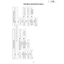
TROUBLE SHOOTING TABLE
No picture and No sound
Check all the settings microprocessor's adjust process menu.
Do F3301 and F3302
function?
Are T3701's secondary
outputs, +34V, +9V, +5V
and -11V normal?
Remove F3301 and F3302
and check the load side.
Is there short-circuiting?
Is there short-circuiting of
T3701 primary side periphery,
Q3703, Q3704 and S4701.
Replace F3301 and F3302.
Check S4701 and
connection cable.
Is T3701's primary oscillator
waveform normal?
Check T3701's secondary
load.
Yes
Yes
No
No
No
No
No
Yes
Check J3701 periphery and
connection cable.
Replace F6500~F6501.
Is the pin (120) of IC1201 in
the "H" state?
Is the output of Q3606 in the
"L
" state?
Yes
Yes
No
No
No
Yes
Yes
Check the OFL1 line, IC1201
and their peripheral parts.
Check the OFL line, Q3606
and their peripheral parts.
Check T6500~T6503,
Q6500~Q6505 and
connection cable.
Back light lamp failure to light up
Is the primary side of
T6500 ~T6503 periphery
short-circuiting?
Replace the back light lamp
with new one and check
again.
18
LC-13B4E
LC-15B4E
LC-15B4E
TROUBLE SHOOTING TABLE
(Continued)
No picture (1/3)
Check all the settings microprocessor's adjust process menu.
Is in/output of
IC801 normal?
Is in/output of
IC1201 normal?
Check IC801
and its
peripheral parts.
Check IC1201
and its
peripheral parts.
Check LCD
panel voltages
and waveform.
Yes
Yes
No
No
No picture
at all
Is voltages at
pins (6), (7) and
(18) tuner
normal?
Is output at pin
(13) of tuner
normal?
Check the
power line.
Check tuner
and its
peripheral parts.
Is input at pin
(16) of IC806
normal?
Is the pin (3) of
IC806 at "H"
state?
Yes
Yes
No
No
No
No
No
Yes
No TV output
Is the pin (48)
of IC2001 at "H"
state?
Yes
Check the its
line.
Check the its
line.
Check IC806
and its
peripheral parts.
Is input at pin
(14) of IC806
normal?
Check V1_V
line and its
peripheral parts.
No
No VIDEO 2
output
19
LC-13B4E
LC-15B4E
LC-15B4E
TROUBLE SHOOTING TABLE
(Continued)
No picture (2/3)
Check all the settings microprocessor's adjust process menu.
Is input at pin
(14) of IC806
normal?
Check the V2_V
line and its
peripheral parts.
No
No VIDEO 1
output
Check the SY-line,
SC-line and their
peripheral parts.
Is input at pin (9)
of IC806 and pin
(1) of IC803
normal?
No
No S-VIDEO
output
Check IC1201
and its
peripheral parts.
No
Yes
Yes
No TELETEXT
output
Is input at pins
(136), (137), (138),
and (142) of
IC1201 normal?
No
Check the R, G
and B line.
Is output at pins
(57)~(59) of IC1601
normal?
No
Yes
Check V2VO line
and its peripheral
parts.
Is input at pin (21) of
IC1601 normal?
Check IC1601 and its
peripheral parts.
20
LC-13B4E
LC-15B4E
LC-15B4E
TROUBLE SHOOTING TABLE
(Continued)
No picture (3/3)
Check all the settings microprocessor's adjust process menu.
Is output of
R0~R7
normal?
Is output of
G0~G7
normal?
Is output of
B0~B7
normal?
Yes
Yes
No
No
No
Colour is
unusual
Is in/output of
SPIO and
SPOI normal?
No
No picture
image
inversion
No
Gradation
defect
Is output of U/D
normal?
Yes
No
Check R1227 and
its peripheral parts.
Check R1235 and
its peripheral parts.
Check IC1202,
Q1204 and their
peripheral parts.
Check R1228 and
its peripheral parts.
Check R1232 and
its peripheral parts.
Is output V0, V7, V21,
V64, V112, V176,
V235 and V255
normal?
Check IC1101 and its
peripheral parts.
Display

