Sharp LC-150M2E (serv.man2) Service Manual ▷ View online
25
LC-121M2E
LC-150M2E
LC-150M2E
LC-121M2E
LC-150M2E
LC-150M2E
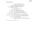
No colour appears
(N358)
(N358)
Is 3.5795 MHz
input into the
pin 10 of IC801?
input into the
pin 10 of IC801?
Check X801 and
its peripheral
parts.
its peripheral
parts.
No colour appears
(N443,PAL)
(N443,PAL)
YES
Is the C/Y signals at pins 13 and 15 of IC801 normal ?
Is the output at pins 10 and 11 of IC2802 normal ?
NO
Check X802 and
its peripheral
parts.
its peripheral
parts.
NO
Is 4.4336 MHz
input into the
pin 8 of IC801?
input into the
pin 8 of IC801?
YES
YES
Check
Peripheral
parts of IC853.
Peripheral
parts of IC853.
NO
Is the composite
signal which is
input into the pins
13 and 15 of
IC801 normal?
signal which is
input into the pins
13 and 15 of
IC801 normal?
Check Peripheral
parts of IC853.
parts of IC853.
NO
YES
Is 4 MHz input
into the pin 8 of
IC2802?
into the pin 8 of
IC2802?
Check X2850
and its peripheral
parts.
and its peripheral
parts.
NO
YES
Check Peripheral
parts of IC2802.
parts of IC2802.
NO
Is the output at pins 29 and 30 of IC2801 normal ?
Is the output at pins 51 and 52 of IC801 normal ?
Check Peripheral parts of IC801.
YES
Check Peripheral
parts of IC2801.
parts of IC2801.
YES
YES
NO
Check Peripheral
parts of IC406.
parts of IC406.
NO
No colour appears
(PAL-M)
(PAL-M)
Check X803 and
its peripheral
parts.
its peripheral
parts.
NO
Is 3.5756 MHz
input into the
pin 9 of IC801?
input into the
pin 9 of IC801?
YES
No colour appears
(SECAM)
(SECAM)
Check X802 and
its peripheral
parts.
its peripheral
parts.
NO
Is 4.4336 MHz
input into the
pin 8 of IC801?
input into the
pin 8 of IC801?
YES
26
LC-121M2E
LC-150M2E
LC-150M2E
LC-121M2E
LC-150M2E
LC-150M2E
A
B
C
D
E
F
G
H
1
2
3
4
5
6
T752
T751
Inverter transformer
IC1201
Controller
SC1201
P402
P302
F703 1.25A 250V
F702 2A 250V
F701
1.25A 250V
P303
P752
IC305 Power AMP.
P403
X802
X803
X801
BLACK
BLUE
RED
IC2001
Micon
P801
SC1202
TP1106
TP1112
T701
DC/DC Transformer
IC2802
X2850
IC853
Digital comb filter
IC2801
1H Dilay system
1H Dilay system
SECAM decoder
IC801 Chroma decoder
TP805
TP804
P2002
P2001
P751
TP1111
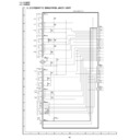
8. CHASSIS LAYOUT
IC1001
AD converter
IC312
Audio control
27
LC-121M2E
LC-150M2E
LC-150M2E
LC-121M2E
LC-150M2E
LC-150M2E
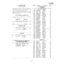
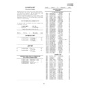
• DESCRIPTION OF SCHEMATIC DIAGRAM
4
TP821 G output
5
TP1107 VCOM
6
TP1108 VO
1. When the exclusive-use AC adapter is used, the color bar signal of color bar generator for service is input
to get the normal screen. When the audio is minimized, the voltage value is measured with the 20 k
Ω
/V tester.
2. When the exclusive-use AC adapter is used, the color density, lightness and color hue are set to the center
position, and the signal of colour bar generator for service is observed to get waveform.
The waveform test point is indicated with the mark ( ) in the wiring diagram.
The waveform test point is indicated with the mark ( ) in the wiring diagram.
3. Indication of resistors and capacitors
[Resistor]
Unit: Nonindication ···
Ω
, K ··· k
Ω
,
M ··· M
Ω
Error: Nonindication ···
±
10%
J ···
±
5%
F ···
±
1%
D ···
±
0.5%
[Capacitor]
Unit: Nonindication or
µ
···
µ
F,
P or p ··· pF
• WAVEFORMS
1
TP804 CSYNC
2
TP820 B output
3
TP819 R output
IMPORTANT SAFETY NOTICE:
PARTS MARKED WITH "
å
"
( )
ARE
IMPORTANT FOR MAINTAINING THE SAFETY
OF THE SET.
BE SURE TO REPLACE THESE PARTS WITH
SPECIFIED ONES FOR MAINTAINING THE SAFE-
TY AND PERFORMANCE OF THE SET.
OF THE SET.
BE SURE TO REPLACE THESE PARTS WITH
SPECIFIED ONES FOR MAINTAINING THE SAFE-
TY AND PERFORMANCE OF THE SET.
CAUTION:
This circuit diagram is original one, therefore there
may be a slight difference from yours.
may be a slight difference from yours.
Resistor
Capacitor
Nonindication
Carbon-film resistor
Nonindication
Ceramic capacitor
C
Solid resistor
ML
Mylar capacitor
S
Metal-oxide-film resistor
PF
Polypropylene
N
Metal-film resistor
film capacitor
W
Cement resistor
TA
Tantalum capacitor
T
Special resistor
ST
Styrol capacitor
[Item]

