Sharp 66GS-62 (serv.man24) Service Manual / Technical Bulletin ▷ View online
CTV 2004 03 04
Month of Issue:
March 2004
Classification:
White
TELEVISION TECHNICAL BULLETIN
Page 2 of 2
Sharp Electronics (UK) Limited
Reference AvW 10 03 2004 - 4
Revision 1
White – Carry out as required
Yellow – Carry out as required and whenever the unit comes in for service
Red – Carry out on all units
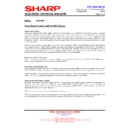
Low audio levels on SCART inputs
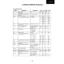
This normally happens after the NVM has been blanked. Set up the NVM as follows:
This normally happens after the NVM has been blanked. Set up the NVM as follows:
24645 Type NVM
24C16 Type NVM
Page
Address
Value
Page
Address
Value
08
72
2A
03
4E
14
08
73
00
03
4F
00
03
50
14
03
51
00
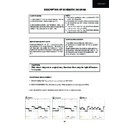
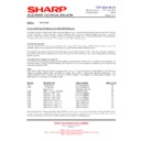
Red, Green and Blue Lines at the Top of the Picture
Lines at the top of the picture can be caused by corruption of the memory, check and set the NVM locations as follows.
The fault can also happen if the +25V is low to the vertical flyback circuit or if there is a fault in the vertical, reducing the
flyback level.
Lines at the top of the picture can be caused by corruption of the memory, check and set the NVM locations as follows.
The fault can also happen if the +25V is low to the vertical flyback circuit or if there is a fault in the vertical, reducing the
flyback level.
24645 Type NVM
24C16 Type NVM
Page
Address
Value
Page
Address
Value
0C
EB
10
05
D6
10
0C
F7
1A
05
E2
1A
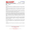
Low Brightness in the Service Mode Only
Due to a corruption in the EEPROM, when entering the service mode on some earlier GA10 chassis’s, the picture is
dark. By using the channel up button to step to one of the RGB gain settings, the brightness will increase to a
watchable level. Service adjustments can now be carried out normally.
Due to a corruption in the EEPROM, when entering the service mode on some earlier GA10 chassis’s, the picture is
dark. By using the channel up button to step to one of the RGB gain settings, the brightness will increase to a
watchable level. Service adjustments can now be carried out normally.
This is not considered to be a major problem as it does not affect the customers viewing. To cure the problem would
require replacing IC1002 and IC1003.
require replacing IC1002 and IC1003.
REF NO
DESCRIPTION
PART NUMBER
PRICE CODE
-
Blanking Jig for 24645
GS-SERV-JIG01
AZ
-
Blanking Jig for 24C16
GS-SERV-JIG02
AZ
IC1002
EEPROM
Depends upon chassis – See parts issue Technical Bulletin
IC1003
NVM
Depends upon chassis – See parts issue Technical Bulletin
Note that the list of components given above IS NOT a parts list to cure all memory and processor related problems in
this chassis. It has been compiled to show all the part numbers for items refered to in this document. If the parts noted
in the text are not faulty, carry out fault finding procedures to locate the problematic part.
this chassis. It has been compiled to show all the part numbers for items refered to in this document. If the parts noted
in the text are not faulty, carry out fault finding procedures to locate the problematic part.
Display

