Sharp 66GS-62 (serv.man17) Service Manual / Technical Bulletin ▷ View online
CTV 2004 03 02
Date of Issue: 10
th
November 2004
Classification:
White
TELEVISION TECHNICAL BULLETIN
Page 1 of 3
Sharp Electronics (UK) Limited
Reference AvW 10 03 2004 - 2
Revision 4
White – Carry out as required
Yellow – Carry out as required and whenever the unit comes in for service
Red – Carry out on all units
MODEL
66GS62H
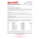
Power Supply Problems with the GA10 Chassis
Power Factor Circuit
When fault finding on the power supply fitted to the GA10 chassis, it is important to note that its ability to regulate
correctly is dependent upon the power factor circuit output. The power factor circuit sits between the mains bridge
rectifier and the resonant power supply. When the set is first turned on, its operation is muted and the supply generated
across C713 will be approximately 320VDC. Once the power supply is operational, the supply across C713 will
increase to 420VDC. The set will operate without the power factor circuit turning on, but it may be intermittent, or start
up, then shut down.
While the set is starting up, the supply to the power factor control IC, IC701 is about 8.8VDC, but when operational it
will be about 14.5VDC. Note that all voltages are taken with reference to the negative end of C713. This supply is
taken from pin 7 of the chopper transformer via R718, D737 and C709. Note that the mute circuit that operates on the
power factor circuit is dependent on the base voltage of Q704. If the base voltage rises to 10.7V (its emitter being fixed
at 6.8V by D714), then the mute is released and the power factor circuit will operate.
Power Factor Circuit Correction
There is a misprint on the schematic diagram. Between the supply line and the emitter of Q704, a 2.2k
There is a misprint on the schematic diagram. Between the supply line and the emitter of Q704, a 2.2k
Ω
SMD resistor
is fitted. Zener diode D714 is connected to the emitter of Q704.
Set Comes on then Shuts Down
Either reprogram or blank the NVM. This problem may cause the power supply to go into the standby mode, or just
inhibit the line or east/west drive signals. Checking waveforms and voltages may be misleading with this fault scenario.
Either reprogram or blank the NVM. This problem may cause the power supply to go into the standby mode, or just
inhibit the line or east/west drive signals. Checking waveforms and voltages may be misleading with this fault scenario.
Another possibility is that the power factor circuit has not started up. This can be caused by a number of items, but
check R718, D737, C709 and the operation of the mute circuit based around Q704 and Q705.
check R718, D737, C709 and the operation of the mute circuit based around Q704 and Q705.
Dead set (no power supply output)
No power factor corrector or power supply operation. This normally means that the power factor circuit has failed and
the mains input fuse is open circuit. Check and replace D736, D739, and Q701. If Q701 is short circuit, it is likely that
R714 has gone open circuit causing R705 to go faulty and resulting in Q720, Q721 and IC701 failing. In this situation
replace R705, R714, Q720, Q721 and IC701.
C713 can sometimes go short circuit, although this is not common.
C716 (coupling capacitor from the start up circuit) can go open circuit causing the power supply to stop operation. The
start up oscillator will continue to run and series of pulses will be seen at the junction of R781 and C716.
start up oscillator will continue to run and series of pulses will be seen at the junction of R781 and C716.
CTV 2004 03 02
Date of Issue: 10
th
November 2004
Classification:
White
TELEVISION TECHNICAL BULLETIN
Page 2 of 3
Sharp Electronics (UK) Limited
Reference AvW 10 03 2004 - 2
Revision 4
White – Carry out as required
Yellow – Carry out as required and whenever the unit comes in for service
Red – Carry out on all units
Dead set (low or no power supply output)
If the power supply does not kick off - start up oscillator running, but Q702 and Q703 not energising the chopper
transformer - the HT will be low (up to 40V) or zero. Q702 or Q703 breaking down internally can cause this, even
though they can measure all right on a meter.
If the power supply does not kick off - start up oscillator running, but Q702 and Q703 not energising the chopper
transformer - the HT will be low (up to 40V) or zero. Q702 or Q703 breaking down internally can cause this, even
though they can measure all right on a meter.
If the feedback from the voltage feedback circuit based around he opto-coupler, IC703 is incorrect then the HT will fail
to rise. Q713 has been known to fail short circuit, but other components in this area can cause the same fault.
to rise. Q713 has been known to fail short circuit, but other components in this area can cause the same fault.
Intermittent Operation
Unit intermittently will not start up from standby, shuts down or the line collapses. Q606 failing intermittent, it may read
perfectly alright on a component test. This transistor is part of the protection feedback circuit.
Unit intermittently will not start up from standby, shuts down or the line collapses. Q606 failing intermittent, it may read
perfectly alright on a component test. This transistor is part of the protection feedback circuit.
Set Enters Standby at Switch On
There is a protection line that monitors the outputs to the loudspeakers. If this output becomes unbalanced, then the
protection pin on the processor (pin 63 - PROT) will go low, putting the set into standby. This normally happens if the
loudspeakers are left unplugged when servicing the set. Depending upon the component tolerances on the chassis,
this fault can also happen intermittently while the set is running.
Takes a Long Time to start up or may not start up at All
There are two possible causes of this problem - D724 can go leaky or short circuits, reducing the +5V supply, or the
processor can fail. There are two different types of microprocessor fitted to this model depending upon the size of the
EEPROM (IC1003). See parts issues Technical Bulletin for more information on this.
Intermittent Turning On
When the set is left in standby, it may turn on. This fault can be very intermittent. This problem is caused by failure of
C1013.
When the set is left in standby, it may turn on. This fault can be very intermittent. This problem is caused by failure of
C1013.
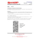
Location of C1013 on the Print Side of the PWB
Intermittent line collapse or turning off
This problem can be caused by one of the HT feedback resistors (R742, R743, R744 and R745) on the secondary of
the power supply. Usually it is R743 that fails and it is best to check this component by substitution as the fault may not
respond to flexing the PWB.
This problem can be caused by one of the HT feedback resistors (R742, R743, R744 and R745) on the secondary of
the power supply. Usually it is R743 that fails and it is best to check this component by substitution as the fault may not
respond to flexing the PWB.
CTV 2004 03 02
Date of Issue: 10
th
November 2004
Classification:
White
TELEVISION TECHNICAL BULLETIN
Page 3 of 3
Sharp Electronics (UK) Limited
Reference AvW 10 03 2004 - 2
Revision 4
White – Carry out as required
Yellow – Carry out as required and whenever the unit comes in for service
Red – Carry out on all units
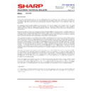
REF NO
DESCRIPTION
PART NUMBER
PRICE CODE
C1013
SMD Capacitor
VCKYTV1CF105Z*
AA
C709
Capacitor, 10
µ
F 50V
VCEAGA1HW106M
AH
C713
Capacitor, 68uF 450V
RC-EZ0141BMZZ
AL
C716
SMD Capacitor, 6.8nF 50V
VCKYTV1HB682K
AA
D724
SMD Zener Diode, 2V4
RH-EX0574BMZZ
AA
D736
Diode, IN4937
RH-DX0579BMZZ
AB
D737
SMD Diode, LL4148
RH-DX0551BMZZ
AA
D739
Zener Diode, 33V
RH-EX0427BMZZ
AA
F701
Fuse, 3.15AH 20mm
QFS-C3226CEZZ
AE
IC1001
Microprocessor (NVM 24C16)
RH-IX1856BMZZ
BA
IC1001
Microprocessor (NVM 24645)
RH-IX1798BMZZ
BA
Q606
SMD Transistor, 2SC2412
VS2SC2412KQ-1
AA
Q701
Transistor, 2SK2662
CH-TX0231BMV0
AK
Q702
Transistor, 2SK2662
CH-TX0231BMV0
AK
Q703
Transistor, 2SK2662
CH-TX0231BMV0
AK
Q713
SMD Transistor, 2SA1037
VS2SA1037KQ-1
AA
Q715
SMD Transistor, 2SA1037
VS2SA1037KQ-1
AA
Q720
SMD Transistor, 2SC2412
VS2SC2412KQ-1
AA
Q721
SMD Transistor, 2SA1037
VS2SA1037KQ-1
AA
Q725
SMD Transistor, BC847
RH-TX0232BMZZ
AA
R705
SMD Resistor, 8.2k 1/10W
VRS-TV1JD822J
AA
R714
Resistor, 0.56R 2W
VRN-VV3LBR56J
AB
R718
Resistor, 10
Ω
0.5W
RR-XZ0212BMZZ
AB
R742
SMD Resistor, 120K
Ω
1%
VRS-TQ2BD124F
AA
R743
SMD Resistor, 120K
Ω
1%
VRS-TQ2BD124F
AA
R744
SMD Resistor, 3.9K
Ω
1%
VRS-TV1JD392J
AA
R745
SMD Resistor, 470K
Ω
1%
VRS-TV1JD473J
AA
R753
SMD Resistor, 22k
Ω
VRS-CY1JF222J
AA
Note that the list of components given above IS NOT a parts list to cure all power related problems in this chassis. It
has been compiled to show all the part numbers for items refered to in this document. If the parts noted in the text are
not faulty, carry out fault finding procedures to locate the problematic part.
has been compiled to show all the part numbers for items refered to in this document. If the parts noted in the text are
not faulty, carry out fault finding procedures to locate the problematic part.
Display

