Sharp 66GF-63 (serv.man3) Service Manual ▷ View online
DA100 (50Hz) and DA50W Chassis – Repair Notes
Page 4 of 80
Sharp Electronics (UK) Limited - May 2003
Revision 3
Analogue to Digital Converters .................................................................................. 57
Digitally Controlled Clock Oscillator ............................................................................ 57
Analogue Video Output........................................................................................... 57
Average Beam Current Limiting ................................................................................. 57
Protection Circuitry .............................................................................................. 57
Scan Velocity Modulation Output ............................................................................... 58
Protection – Video/Sync Processor.............................................................................. 58
Safety.......................................................................................................................................................................................58
Vertical Protection (VPROT)...............................................................................................................................................58
Vertical Protection (VPROT)...............................................................................................................................................58
Faults Connected to the VDP.................................................................................... 59
Picture Rotation................................................................................ 60
Circuit Description ............................................................................................... 60
Scan Velocity Modulator ...................................................................... 61
Circuit Description ............................................................................................... 61
Faults in the Picture Rotation and Scan Velocity Modulator Circuit ......................................... 62
Faults in the Picture Rotation and Scan Velocity Modulator Circuit ......................................... 62
Preventative Maintenance ..................................................................... 63
Servicing Tips .................................................................................. 64
Error Codes....................................................................................................... 67
Part Changes ................................................................................... 68
Remote Control Battery Covers ................................................................................. 68
CRT Types ........................................................................................................ 68
CRT Types ........................................................................................................ 68
Service Mode .................................................................................. 69
Entering the Service Mode ...................................................................................... 69
Geometry Adjustments........................................................................................... 70
G2 Setting ........................................................................................................ 70
G2 Adjustment ................................................................................................... 70
Grey Scale Adjustment .......................................................................................... 71
Voltage Tables ................................................................................. 72
IC1001 – Microprocessor ........................................................................................ 73
IC801 – Video Sync Processor (VDP) ........................................................................... 74
IC305 – Multiple Sound Processor (MSP)....................................................................... 75
IC1801 – Cathode Drive Amplifier (CDA) ...................................................................... 76
IC301 / IC302 - Audio Amplifiers ............................................................................. 77
IC702 - Primary Control ........................................................................................ 77
IC501 - Vertical Output ........................................................................................ 78
IC1003 - NVM ................................................................................................... 78
IC2401 - Megatext.............................................................................................. 79
IC201 - IF ....................................................................................................... 80
DA100 (50Hz) and DA50W Chassis – Repair Notes
Page 5 of 80
Sharp Electronics (UK) Limited - May 2003
Revision 3
Figures
Figure 1: DA100 (50Hz) Chassis – model 56FW53H .................................................................................................................7
Figure 2: Power Supply Layout (Component Side).................................................................................................................... 13
Figure 3: Power Supply Component Locations (Print Side) .................................................................................................... 13
Figure 4: Location of Supply Measurement Points................................................................................................................... 14
Figure 5: Power Supply Schematic Diagram.............................................................................................................................. 15
Figure 6: Q701 Gate Waveform................................................................................................................................................... 16
Figure 7: Standby Power Supply .................................................................................................................................................. 17
Figure 8: Degauss Circuit .............................................................................................................................................................. 18
Figure 9: +5V Generation Circuit ................................................................................................................................................. 19
Figure 10: 3.3V Regulation Circuit............................................................................................................................................... 19
Figure 11: Location of R792 ..........................................................................................................................................................20
Figure 12: Location of R623..........................................................................................................................................................20
Figure 13: Power Factor Circuit (56FW53H)............................................................................................................................ 21
Figure 14: Power Factor Correction PWB – 66 and 76cm Models (PWB on left)..............................................................22
Figure 15: 56FW53H Power Factor Correction PWB..............................................................................................................22
Figure 16: Location of 56FW53H Power Factor PWB.............................................................................................................22
Figure 17: Location of D735 .........................................................................................................................................................23
Figure 18: Location of Audio Stage components (Main PWB) ...............................................................................................23
Figure 19: Location of Centre Speaker PWB ............................................................................................................................24
Figure 20: Location of Components on the CRT PWB .............................................................................................................24
Figure 21: Location of SMD Capacitor on IC708 .....................................................................................................................25
Figure 22: Horizontal Output Stage...........................................................................................................................................27
Figure 23: Location of Horizontal Stage Components ............................................................................................................28
Figure 24: Q601 Base Drive Waveform .....................................................................................................................................28
Figure 25: GF Focus Modulator Circuit ......................................................................................................................................29
Figure 26: Picture of the FW Focus Modulator PWB .............................................................................................................29
Figure 27: FW Focus Modulator Circuit.....................................................................................................................................30
Figure 28: Location of Link Wire JL2 ........................................................................................................................................ 31
Figure 29: East West Circuit .......................................................................................................................................................32
Figure 30: East/West Circuit – Print Side................................................................................................................................33
Figure 31: East/West Circuit - Component Side......................................................................................................................33
Figure 32: East/West Drive Waveform - Pin 32 of IC801....................................................................................................34
Figure 33: 66cm and 76cm CRT PWB .........................................................................................................................................36
Figure 34: 56FW53H CRT PWB...................................................................................................................................................36
Figure 35: Vertical Output Amplifier.........................................................................................................................................38
Figure 36: Vertical Fly-back Circuit ...........................................................................................................................................39
Figure 37: Vertical Protection Signal (VPROT - Pin 11 of IC801) ........................................................................................39
Figure 38: Vertical Scan Coil Waveform - Top of Coil ...........................................................................................................40
Figure 39: Vertical Scan Coil Waveform - Bottom of Coil.....................................................................................................40
Figure 40: Vertical Stage - Component Side ............................................................................................................................ 41
Figure 41: Vertical Stage - Print Side........................................................................................................................................ 41
Figure 42: Audio Amplifier Circuit (left channel)....................................................................................................................43
DA100 (50Hz) and DA50W Chassis – Repair Notes
Page 6 of 80
Sharp Electronics (UK) Limited - May 2003
Revision 3
Figure 43: Centre Speaker PWB Location................................................................................................................................44
Figure 44: Centre Speaker Circuit Diagram..............................................................................................................................44
Figure 45: Centre Speaker Modification 1 ................................................................................................................................45
Figure 46: Centre Speaker PWB Modification 2......................................................................................................................46
Figure 47: Pro-Logic PWB..............................................................................................................................................................47
Figure 48: Dolby Pro-Logic Circuit Diagram (66GF64H)........................................................................................................48
Figure 49: Dolby Pro-Logic PWB Connector ..............................................................................................................................49
Figure 50: Communication Block Diagram ..................................................................................................................................50
Figure 51: Reset Timing ................................................................................................................................................................. 51
Figure 52: Audio Protection Circuit ............................................................................................................................................52
Figure 53: Horizontal Mute Circuit.............................................................................................................................................52
Figure 54: AV Link Schematic Diagram......................................................................................................................................53
Figure 55: Internal Architecture of IC801 (VDP 3120) ........................................................................................................56
Figure 56: VDP Protection Circuits .............................................................................................................................................58
Figure 57: Position of C824 ..........................................................................................................................................................59
Figure 58: Picture Rotation Circuit (located on CRT PWB) ...................................................................................................60
Figure 59: Scan Velocity Modulator Circuit.............................................................................................................................. 61
Figure 60: SVM and Tilt Coil Connectors...................................................................................................................................62
Figure 61: CRT Base PWB Modification (66cm and 76cm sets only) ...................................................................................63
Figure 62: Fault Finding Flow Chart 1.........................................................................................................................................65
Figure 63: Fault Finding Flow Chart 2 ........................................................................................................................................66
Figure 64: LED Fault Code Table.................................................................................................................................................67
Figure 65: HW OPC LED Error Code Jig ...................................................................................................................................67
DA100 (50Hz) and DA50W Chassis – Repair Notes
Page 7 of 80
Introduction
The DA100 (50Hz) chassis and its derivatives (DA50W) are fitted in many Sharp widescreen television sets.
Production started in 1999 with the FW models and continued up to the HW models. There have been a number
of changes to the circuit configuration, layout and operation but the overall circuit theory and fault finding
techniques remain the same for all chassis.
This article will endeavour to assist the engineer in various faultfinding procedures that have been found to be
beneficial in reducing repair times and cost. One important item to note is that the large and expensive
(microprocessor, VDP, MSP, etc) IC’s only rarely fail.
It is worthwhile considering that there have been a number of different types of CRT used with this chassis for
the same model type. Philips, Thomson (Videocolor) and LG CRT have been used. Note that the scanning coils are
supplied with the CRT and therefore the horizontal output stage components will be different for different CRT
types. With the Philips CRT there are two focus anodes, so the fly-back transformer is also different in these
models.
Most of the problems on this chassis are related to either the power circuits (chopper and horizontal) or
memory. Resetting or replacing the memory can easily cure many faults that appear to lie in the picture
processing circuitry or drive areas.
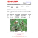
Figure 1: DA100 (50Hz) Chassis – model 56FW53H
Sharp Electronics (UK) Limited - May 2003
Revision 3

