Sharp 51GT-25 (serv.man2) Service Manual ▷ View online
9
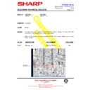
51GT-25H
PAGE
ADDRESS
DESCRIPTION
VALUE
A6
10
A7
02
A8
00
A9
30
AA
04
AB
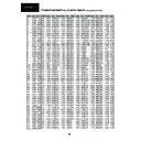
PAGE MEMORY FOR LIST MODE PROGRAM 1
00
AC
10
AD
02
AE
00
AF
30
B0
04
B1
PAGE MEMORY FOR LIST MODE PROGRAM 2
00
B2
10
B3
02
B4
00
B5
30
B6
04
B7
PAGE MEMORY FOR LIST MODE PROGRAM 3
00
B8
10
B9
02
BA
00
BB
30
BC
04
BD
PAGE MEMORY FOR LIST MODE PROGRAM 4
00
BE
10
BF
02
C0
00
C1
30
C2
04
C3
PAGE MEMORY FOR LIST MODE PROGRAM 5
00
C4
10
C5
02
C6
00
C7
30
C8
04
C9
PAGE MEMORY FOR LIST MODE PROGRAM 6
00
CA
10
CB
02
CC
00
CD
30
CE
04
CF
PAGE MEMORY FOR LIST MODE PROGRAM 7
00
1
D0
∼ FF
RESERVED
FF
{
Page 100
{
Page 200
{
Page 300
{
Page 400
DEFAULT LIST MODE PAGES MEMORIZATION NOTE:
In page memory for LIST MODE, every digit is written in one nibble (4 bits).
The default values for programs 0
The default values for programs 0
∼7 are as follows: 100, 200, 300, 400.
Example: Program 0
NVM Position:
A0
A1
A2
A3
A4
A5
{
0
{
2
{
0
{
0
{
3
{
0
{
0
{
4
{
0
{
0
{
1
{
0
NVM Value:
10
51GT-25H
Fig. 4
c) When
∨
button is pressed, upper picture scanning increases and
lower picture scanning decreases.
d) Adjust the vertical symmetry to obtain symmetrical scanning between
upper and lower picture (Fig.4).
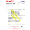
1. HOR SHIFT
a) Receive Philips pattern signal.
b) When
a) Receive Philips pattern signal.
b) When
∧
button is pressed, picture moves to the left.
c) When
∨
button is pressed, picture moves to the right.
d) Adjust the horizontal location to obtain picture centering (Fig.1).
•GEOMETRY ADJUSTMENT PROCEDURE
2. VERT SHIFT
a) Receive Philips pattern signal.
b) When
a) Receive Philips pattern signal.
b) When
∧
button is pressed, picture moves up.
c) When
∨
button is pressed, picture moves down.
d) Adjust the vertical location to obtain picture centering (Fig.2).
3. VERT AM
a) Receive Philips pattern signal.
b) When
a) Receive Philips pattern signal.
b) When
∧
button is pressed, vertical size of picture increases.
c) When
∨
button is pressed, vertical size of picture decreases.
d) Adjust the vertical size to obtain picture overscan (Fig.3).
Fig. 2
Fig. 1
4. VERT SLOP
Fig. 3
a) Receive Philips pattern signal.
b) When
∧
button is pressed, upper picture scanning decreases and
lower picture scanning increases.
•••••PIF/AGC Adjustment
•••••Screen Adjustment
3. Focus Adjustment
Set contrast to 10/10, brightness to 5/10 and
colour 0/10.
colour 0/10.
Apply mains voltage of 220V AC/50HZ to TV.
1.
Receive Philips pattern signal to a level between
60 and 80 dB
60 and 80 dB
µV.
2
.
3
.
Adjust focus potentiometer to obtain
maximum definition.
maximum definition.
4
.
1. AFT Adjustment
AFT must be adjusted to a fixed value of 40.
Receive the «COLOUR BAR» signal (Channel E-
12).
12).
Signal strength: 57 dBµV.
2. RF-AGC Cut-In Adjustment (I2C BUS)
Switch set OFF and ON again, setting is now
memorized.
memorized.
1
.
Enter into Service Mode.
2
.
Push CH
∧
until AGC appears on screen.
3
.
4
.
Push key of R/C.Setting is made
automatically. During this setting the colour bar
shall go from red to yellow. When setting is
finished, colour bar disappears and B-STOP
(bus stop)is shown on screen.
automatically. During this setting the colour bar
shall go from red to yellow. When setting is
finished, colour bar disappears and B-STOP
(bus stop)is shown on screen.
5
.
4. G2 Adjustment
the screen VR of FBT.
5
.
Check BKGD. If it is necessary adjust BKGD
according to instructions detailed in the next
page.
page.
Apply mains voltage of 220V AC/50HZ to TV.
1.
Receive the «MONOSCOPE» pattern signal to a
level between 60 and 80 dB
level between 60 and 80 dB
µV.
2
.
3
.
4
.
Enter into Service Mode. Press the TEXT key of
R/C and set to level.
R/C and set to level.
Set to the point where the raster disappears on
11
51GT-25H
1. Y-DLY
ALTERNATIVE CRT:
See below detailed information in order to adapt from THOMSON ↔ PHILIPS CRT.
See below detailed information in order to adapt from THOMSON ↔ PHILIPS CRT.
THOMSON CRT
PHILIPS CRT
PARTS
REF.
REF.
PARTS CODE
DESCRIPTION
PARTS CODE
DESCRIPTION
CRT
VB51EFS83912E
21” CRT
VB51EAL15511N
21” CRT
R609
VRN-VV3ABR82J
0.82Ω 1W
VRN-VV3AB3R3J
3.3Ω 1W
C606
RC-FZ6394BMNJ
390nF 250V
RC-FZ6474BMNJ
470nF 250V
(F) wire
CSOCN0460BMV4
(F)
NVM data
Data 24
Address 58
Data 22
Address 58
a) Receive Philips pattern signal.
b) When
b) When
∧
button is pressed, luma phase delays.
c) When
∨
button is pressed, chroma phase delays.
d) Adjust the chroma-luma delay.
•COLOUR ADJUSTMENT PROCEDURES
2. «B-GAIN», «G-GAIN», «R-GAIN»
a) Adjust G2.
b) Tune a white pattern
c) Adjust colour to minimum.
d) Position colourmeter in the center of screen.
e) Using brightness and contrast buttons, select a luminance of »120 nits.
f) Operate again in Service Mode and select location R-GAIN and B-GAIN
to obtain colour coordinates:
b) Tune a white pattern
c) Adjust colour to minimum.
d) Position colourmeter in the center of screen.
e) Using brightness and contrast buttons, select a luminance of »120 nits.
f) Operate again in Service Mode and select location R-GAIN and B-GAIN
to obtain colour coordinates:
X = 0.290 ± 0.015
Y = 0.284 ± 0.015
Y = 0.284 ± 0.015
g) Exit Service Mode and check colour coordinates «X» and «Y» at 20 and 120 nits. It may be
necessary to repeat the same procedure or re-adjust the cuts as show the be below one.
necessary to repeat the same procedure or re-adjust the cuts as show the be below one.
NOTE: Locations «R» alter «X» coordinates; «G» alter «Y» coordinates; «B» alter «X» and «Y»
coordinates.
coordinates.

