Sharp 32JF-77 (serv.man5) Service Manual ▷ View online
10
32JF-77H
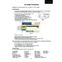
G2 Adjustment
Follow the procedure below to set the G2:
1. Tune the set to the output of a signal generator (Cross-Hatch pattern).
2. In the user menu, set contrast to 80/100 and brightness to 40/100.
3. Connect the oscilloscope to the RED catode of cathode tube (pin 8 of CRT
socket) and adjust G2 to read 150V on the sensor pulse as in figure 16.
2. In the user menu, set contrast to 80/100 and brightness to 40/100.
3. Connect the oscilloscope to the RED catode of cathode tube (pin 8 of CRT
socket) and adjust G2 to read 150V on the sensor pulse as in figure 16.
Note:
Oscilloscope should be adjusted for vertical TV field trigger and synchronized with video signal.
Oscilloscope should be adjusted for vertical TV field trigger and synchronized with video signal.
Vertical bow
Adjust the Vertical bow so that the picture is centred.
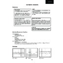
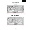
The effect of this adjustment is shown in figure 12.
The effect of this adjustment is shown in figure 12.
• When the volume up button is pressed, the vertical bow changes to left.
• When the volume down button is pressed, the vertical bow changes to right.
• Press the stand-by button on the remote control to store.
Vertical size
Adjust the Vertical size so that 8% over-scan is achieved.
The effect of this adjustment is shown in figure 13.
The effect of this adjustment is shown in figure 13.
• When the volume up button is pressed, the vertical size of the picture increases.
• When the volume down button is pressed, the vertical size of the picture decreases.
• Press the stand-by button on the remote control to store.
Vertical S-correction
Adjust the Vertical S-correction so that the picture symmetrical between the top, centre and
bottom. The effect of this adjustment is shown in figure 14.
bottom. The effect of this adjustment is shown in figure 14.
• When the volume up button is pressed, the top and bottom scanning decreases and the
centre scanning increases.
• When the volume down button is pressed the top and bottom scanning increases and the
centre scanning decreases.
• Press the stand-by button on the remote control to store.
Vertical Shift
Adjust the Vertical Shift so that the picture is centred.
The effect of this adjustment is shown in figure 15.
The effect of this adjustment is shown in figure 15.
• When the volume up button is pressed, the picture moves up.
• When the volume down button is pressed, the picture moves down.
• Press the stand-by button on the remote control to store.
Figure 15
Figure 12
Figure 13
Figure 14
150 V
CH1 gnd
Figure 16
11
32JF-77H
G2 Adjustment (Alternative Method)
Follow the procedure below to set the G2:
1. Tune the set to the output of a signal generator (Cross-Hatch pattern).
2. In the user menu, set the picture levels to the FACTORY settings (normalized)
3. Connect a DC voltimeter at the Red cathode (Pin 8 CRT socket) and adjust G2 to read 145V
2. In the user menu, set the picture levels to the FACTORY settings (normalized)
3. Connect a DC voltimeter at the Red cathode (Pin 8 CRT socket) and adjust G2 to read 145V
DC (
±
5V).
Colour Adjustments
The following adjustments should only be carried out when the CRT or IC850, IC851 and IC852 are replaced.
Follow the procedure below to set the Cut Off.
Do not change the Cut RED value (50%).
1. Adjust G2.
2. Tune a white pattern.
3. Adjust colour to minimum.
4. Position colorimeter in the centre of screen.
5. Adjust brightness and contrast to obtain a luminance of »20 NITS.
6.Operate in Service Mode and select location GREEN CUT OFF and BLUE CUT OFF, to obtain colour
coordinates:
2. Tune a white pattern.
3. Adjust colour to minimum.
4. Position colorimeter in the centre of screen.
5. Adjust brightness and contrast to obtain a luminance of »20 NITS.
6.Operate in Service Mode and select location GREEN CUT OFF and BLUE CUT OFF, to obtain colour
coordinates:
X=0.290 ± 0.015 Y=0.284 ± 0.015
To increase press volume-up button and to decrease press volume down button.
BLUE CUT OFF
alter «X» e «Y» coordinates.
GREEN CUT OFF alter «Y» coordinate.
Press the Store button of Remote Control to store all values.
Follow the procedure below to set the Cut Off (Alternative Method).
Do not change the Cut RED value (50%).
1. Adjust G2.
2. Tune a grey scale pattern.
3. Adjust colour to minimum.
4.Operate in Service Mode and select location GREEN CUT OFF and BLUE CUT OFF.
5. Adjust these parameters until achieve a correct grey scale tracking.
2. Tune a grey scale pattern.
3. Adjust colour to minimum.
4.Operate in Service Mode and select location GREEN CUT OFF and BLUE CUT OFF.
5. Adjust these parameters until achieve a correct grey scale tracking.
To increase press volume-up button and to decrease press volume down button.
Press the Store button of Remote Control to store all values.
Press the Store button of Remote Control to store all values.
Follow the procedure below to adjust the customer Colour Limit Control (Hot / Cold).
1. Tune a white pattern.
2. Adjust colour to minimum.
3. Position colorimeter in the centre of screen.
4. Adjust brightness and contrast to obtain a luminance of »20 NITS.
5. Operate in Service Mode and select location “Hot Cut RED”, “Hot Cut GREEN” and “Hot Cut BLUE” by
channel up/down buttons of the Remote Control.
6. Press volume up/down to adjust “Hot Cut RED”, “Hot Cut GREEN” and “Hot Cut BLUE” to obtain the colour
limit coordinates (X/Y) for HOT picture variation.
7. Select location ”Cold Cut RED”, “Cold Cut GREEN” and “Cold Cut BLUE” by channel up/down buttons of the
Remote Control.
8. Press volume up/down to adjust “Cold Cut RED”, “Cold Cut GREEN” and “Cold Cut BLUE” to obtain the
colour limit coordinates (X/Y) for COLD picture variation.
9. Press the Store button of Remote Control to store all adjustments.
10. Turn off the receiver by Main switch to exit the Service Mode.
12
32JF-77H
Automatic Gain Control Adjustment (I)
To correctly align the Automatic Gain Control, follow the procedure outlined below:
1. Tune the set into a pattern generator on I-21.
2. Enter the Service Mode.
3. Press the YELLOW button of Remote Control to select “Automatic Gain Control”
4. Press volume up/down to adjust to “109 dB/µV”.
5. It will be stored automatically.
6. Turn off the receiver by Main switch to exit the Service Mode.
2. Enter the Service Mode.
3. Press the YELLOW button of Remote Control to select “Automatic Gain Control”
4. Press volume up/down to adjust to “109 dB/µV”.
5. It will be stored automatically.
6. Turn off the receiver by Main switch to exit the Service Mode.
Subcarrier adjustment (ONLY PAL)
1. Tune the colour bar signal pattern (Subcarrier PAL).
2. Enter the Service Mode.
3. Press channel up/down buttons of Remote Control to select “Subcarrier adjustment”.
4. Press volume up/down buttons of Remote Control to adjust Subcarrier frequency until “OK” appear on screen.
5. Press Stand-by button of Remote Control to store adjust.
6. Turn off the receiver by Main switch to exit the Service Mode.
Changing NVM Data
To change the data contained within the Non Volatile Memory, it is necessary to first select the page the data is stored in,
then the position and finally to change the data itself.
then the position and finally to change the data itself.
NOTE: The values of “Page, Position and Value” start by “0x”. It means that the two next locations are hexadecimal
representations.
The procedure below outlines this process.
representations.
The procedure below outlines this process.
1. Enter the Service Mode.
2. Press the GREEN button of Remote Control to access to “NVM / PAGE”, use the volume up/down buttons to
change this data (data is shown in hexadecimal format).
3. Press the channel up button to select “NVM / POSITION”, use the volume up/down buttons to change this data
(data is shown in hexadecimal format).
4. Press the channel up button to select “NVM / VALUE”, use the volume up/down buttons to change this data (data
is shown in hexadecimal format).
5. Once this data has been set, press the stand-by button to store.
6. If another NVM value has to be changed, use the channel down button to select the page or position and repeat
as necessary.
Note:
Do not change any NVM data, unless you have been advised to do so by a Sharp representative. If data is incorrectly
changed, serious damage may occur to the receiver.
Do not change any NVM data, unless you have been advised to do so by a Sharp representative. If data is incorrectly
changed, serious damage may occur to the receiver.
13
32JF-77H
Flag NVM write ON/OFF
To use this function to rewrite the NVM. It is only necessary when the software of Flash memory (IC6003) change .
1. Enter the Service Mode.
2. Press the Sound mode button(29) of Remote Control. “FLAG NVM WRITE ON” is activated.
3. To exit the Service Mode, press the volume down and channel up buttons on the front of the receiver at the same
time.
4. When “RE-WRITING NVM” appears on the screen, the receiver is now rewriting datas in NVM memory.
5. When the process finish the TV turns off and turn on automatically.
6. After rewriting NVM is necessary to adjust the TV set (Geometries, AGC, G2 and Colour Adjustments)
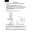
Flag Autoinstall ON/OFF
To use this function to activated Autoinstall mode.
1. Enter the Service Mode.
2. Press MENU button of Remote Control to select “FLAG AUTOINSTALL ON”.
3. Turn off the receiver by Main switch.
4. Turn on the receiver by Main switch.
5. Now the receiver shows the Autoinstallation menu as shown in Figure 17.
2. Press MENU button of Remote Control to select “FLAG AUTOINSTALL ON”.
3. Turn off the receiver by Main switch.
4. Turn on the receiver by Main switch.
5. Now the receiver shows the Autoinstallation menu as shown in Figure 17.
Figure 17: Auto Installation Menu
How To Replace a Damaged NVM by a Blank One
To replace the NVM, follow the procedure outlined below:
Postcode Password Reset
In order to unlock the PostCode when password is not on mind, enter and exit the Service Mode.
Display

