Sharp 32JF-77 (serv.man14) Service Manual ▷ View online
90
32JF-77H
SERVICING NOTES
1. Procedure to reprogram the flash memory (IC6003) contained in the digital module
Equipment needed
• A PC running MS Windows (Windows 98 Second Edition, Windows 2000 or Windows XP).
• A copy of the software “Tiny M2Flash” version 1.07 or higher.
• A PWB7359 (version N1 or higher) digital module including the Micronas SDA6000 microcontroller (also known
as M2) and the Fujitsu MBM29LV160/BE 1Mx16 bit Flash memory. Operation with other devices is not
guaranteed.
• A level-converter circuit to make the {+3.3 V, 0} voltages of the RS232 port at the digital module compatible with
guaranteed.
• A level-converter circuit to make the {+3.3 V, 0} voltages of the RS232 port at the digital module compatible with
the {+12 V, -12 V} voltages of the RS232 port at the PC. This circuit can be built around a MAX3222.
• A power supply to feed the digital module with 3.3 V.
• A power supply to feed the digital module with 3.3 V.
• A RS232 cable for PC (PC-PC Type).
Hardware
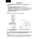
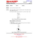
Tiny M2Flash requires the M2 digital module to be connected as shown in figure 18.
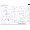
Figure 18: Block diagram showing the hardware Figure 19: Level Converter Schematic Diagram
needed to use Tiny M2Flash.
needed to use Tiny M2Flash.
In order to make the M2 start in the bootstrap loader mode (which is needed to work with Tiny M2Flash), pin 3 of connector
YB must be connected to ground at the moment of resetting the
YB must be connected to ground at the moment of resetting the
digital module (connecting the power to the module
makes it reset). It may also stay connected to ground during the whole programming process, if desired.
Software
The program is composed of two files: One “.exe” and one “.obj” file. The first one contains the MS Windows code that
runs in the PC. The second one contains the machine code that runs in the M2 microcontroller. The “.obj” file must be
moved/copied to “C:\” (there is where the program looks for it.) The program writes into the flash memory the information
runs in the PC. The second one contains the machine code that runs in the M2 microcontroller. The “.obj” file must be
moved/copied to “C:\” (there is where the program looks for it.) The program writes into the flash memory the information
%%8
,
+
@
.
3
2
6
.
9A4A
£..15¤
£261)26¤
(3+((1
8#
)6.6! H$
.
6
/
..
8#
8#
..
(
" $
15
16
14
13
12
11
10
17
18
4
3
5
6
7
8
9
2
1
MAX 3222 CPN
/EN
C1+
V+
C1-
C2+
V-
C2-
T2OUT
R2IN
R2OUT
T2IN
T1IN
R1OUT
R1IN
T1OUT
GND
VCC
/SHDN
CN1
DB9
DB9
CN2
GN0442BM
GN0442BM
LEVEL CONVERTER
3.3VSTBY
2
3
5
4
3
2
1
IC1
.
.
.
.
.
.
.
C2
470nF
C1
470nF
C3
470nF
C4
470nF
C5
470nF
91
32JF-77H
contained in an “.hex” file. This file must conform to the Intel HEX-32 format. The software does check whether the
program operation has been successful or not.
1 Installation of “Tiny M2Flash”:
program operation has been successful or not.
1 Installation of “Tiny M2Flash”:
1.1 Place the “.obj” file in “C:\”.
1.2 Place the “.exe” file anywhere.
1.2 Place the “.exe” file anywhere.
2 “Tiny M2Flash” usage:
2.1 Choose the serial port number that this instance of the program will use to communicate with the digital module.
2.2 Browse the file system and choose the “.hex” file that contains the information to be written into the flash.
2.3 Tie pin 3 of connector YB at the digital module to ground. Turn on the 3.3 V power supply that feeds the digital
module. This will make it reset.
2.4 Press the “PROGRAM” button once. This will automatically:
2.4.1 Open the serial port.
2.4.2 Send the (machine code) “server” program to the M2 microcontroller. The PC will act as the “client.”
2.4.3 Erase the whole flash chip.
2.4.4 Program the flash with the information contained in the “.hex” file.
2.4.2 Send the (machine code) “server” program to the M2 microcontroller. The PC will act as the “client.”
2.4.3 Erase the whole flash chip.
2.4.4 Program the flash with the information contained in the “.hex” file.
2.5 If needed, the button “STOP” can be pressed to stop the execution of that instance of the program in the PC.
However, this will not necessarily interrupt whatever the M2 was doing. It is recommended that the digital module
be resetted after “STOP” has been pressed in the program.
2.6 The program will display the message “OK” or “ERROR,” depending on whether the programming operation has
been successful or not.
2.7 Turn off the power supply.
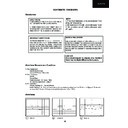
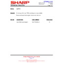
Figure 20: Screenshot of Tiny M2Flash.
Note: The progress bar starts growing right after the flash memory has been erased.
92
32JF-77H
PC COM_
220V./240V. AC 50Hz.
2. GA-200 (M2) FLASH Memory Writer
This Kit is available under request in EPC.
Kit code: CKIT-0001WJV0.
Kit code: CKIT-0001WJV0.
93
32JF-77H
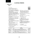
3. Packing of the Set & Accessories
R/C Battery Cover
GCOVHA010WJSA
Remote Control
RRMCG1073BMSA
Batteries
UBATU0013TAZZ
UBATU0013TAZZ
FRONT
SPAKCA549WJZZ
Carton Box
SPAKCA549WJZZ
Carton Box
Wrapper
SPAKP2014BMZZ
SPAKP2014BMZZ
Pack-ad
SPAKX4082BMZZ
SPAKX4082BMZZ
Display

