Sharp 28JW-73H (serv.man2) Service Manual ▷ View online
50Hz Widescreen Colour Television – GA20 Chassis
Sharp Electronics (UK) Ltd
Technical Support
Contents
Switch Mode Power Supply.................................................................................................................. 1
SMPS control IC ............................................................................................................................... 1
Features ........................................................................................................................................ 1
Supply (Pin 1) ............................................................................................................................ 2
Drain (Pin 8................................................................................................................................ 2
Control (Pin 3) ........................................................................................................................... 3
Burst Standby mode............................................................................................................... 3
Hiccup Mode .......................................................................................................................... 3
Demagnetization (Pin 4) ............................................................................................................ 3
Overvoltage............................................................................................................................ 3
Overpower ............................................................................................................................. 3
Current Sense (Pin 5) ................................................................................................................ 3
Short Winding Protection........................................................................................................ 3
Overcurrent ............................................................................................................................ 4
Soft Start ................................................................................................................................ 4
Drive (Pin 6)............................................................................................................................... 4
HT Regulation................................................................................................................................... 4
Standby ............................................................................................................................................ 4
Standby ............................................................................................................................................ 5
Secondary Protection........................................................................................................................ 5
Excessive EHT.............................................................................................................................. 6
CRT Heater Voltage ...................................................................................................................... 6
Horizontal Output Stage ....................................................................................................................... 7
Horizontal Drive Mute ....................................................................................................................... 7
Horizontal Output Theory.................................................................................................................. 7
Vertical Driver..................................................................................................................................... 10
Audio Output ...................................................................................................................................... 12
LOW PASS FILTER........................................................................................................................ 12
Protection ....................................................................................................................................... 13
Mute................................................................................................................................................ 14
Power On .................................................................................................................................... 14
Power Off .................................................................................................................................... 14
Off-Mute1................................................................................................................................. 14
Off-Mute 2................................................................................................................................ 14
Off-Mute 3................................................................................................................................ 14
Microprocessor................................................................................................................................... 15
Supplies.......................................................................................................................................... 15
Reset/Watchdog Circuit .................................................................................................................. 16
I
2
C Bus............................................................................................................................................ 16
Vertical Protection........................................................................................................................... 16
Safety ............................................................................................................................................. 16
LED’s .............................................................................................................................................. 17
50Hz Widescreen Colour Television – GA20 Chassis
Sharp Electronics (UK) Ltd
Technical Support
Issued June 02
Page 1
Switch Mode Power Supply
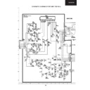
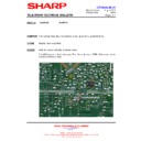
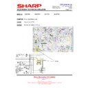
This SMPS consists of a chopper device Q702, Power Factor Correction (PFC) Q703, SMPS
controller IC IC701, current sense R715 and soft start R713 & C706
Q702
R708
27R
R715
0R12
0R12
R713
33K
C706
0.047µf
R711
1K
C704
1000pf
C710
8200pf
C709
470pf
D705
Q703
C718
470pf
470pf
R722
47K
R720
10K
D707 C712
470pf
C713
0.033µf
R721
1K
C717
470pf
470pf
IC701 Pin 6
(Drive)
IC701 Pin 5
(I
sense
)
IC701 Pin 8
(Drain)
4
7
5
9
+ve
T703
Primary
Winding
SMPS
CONTROL
IC
Features
Universal mains supply operation (70 to 276 V AC)
Low external component count (High level of integration).
Valley/zero voltage switching for minimum switching losses
Efficient quasi-resonant operation at high power levels
Frequency reduction at low power standby for improved system efficiency (<3 W)
Burst mode operation for very low standby levels (<1 W)
Internal start-up current source.
Safe restart mode for system fault conditions
Continuous mode protection by means of demagnetization detection (zero switch-on current)
Accurate and adjustable overvoltage protection
Short winding protection
Undervoltage protection (foldback during overload)
Overtemperature protection
Low and adjustable overcurrent protection trip level
Soft (re)start
Mains voltage-dependent operation-enabling level.
50Hz Widescreen Colour Television – GA20 Chassis
Sharp Electronics (UK) Ltd
Technical Support
Issued June 02
Page 2
SUPPLY
MANAGEMENT
internal
supply
UVLO start
VOLTAGE
CONTRLLED
OSCILATOR
FREQUENCY
CONTROL
OVER-
TEMPERATURE
PROTECTION
POWER-ON
RESET
-1
S1
~
MAXIMUM
ON-TIME
PROTECTION
Q
Q
SET
CLR
S
R
UVLO
LODGIC
LODGIC
START-UP
CURRENT SOURCE
VALLEY
DRIVER
LEB
blank
OCP
short
winding
+
+
+
-
-
-
OVERPOWER
PROTECTION
soft
start
OVERVOLTAGE
PROTECTION
+
-
Drain (start)
Demag
Drive
I
sense
4
8
6
5
3
2
1
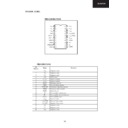
TEA1507
Iss
Supply (Pin 1)
Initially, the IC is self supplying from the rectified mains voltage via pin 8 (drain). External supply
capacitor, C705 at pin 1 is charged by the internal start-up current source to a level of about 4 V or
higher, depending on the drain voltage. Once the drain voltage exceeds the M-level (mains-
dependent operation-enabling level), the start-up current source will continue charging capacitor C705
(switch S1 will be opened, see TEA1507 block diagram). The IC will activate the power converter as
soon as the voltage on pin V
CC
passes the V
CC
(start) level. The IC supply is then taken over by the
secondary winding of T703, (pins 1 and 2), as soon as the output voltage reaches its intended level.
The IC supply from the mains voltage is subsequently stopped for high efficiency operation (green
function).
The moment the voltage on the V
The IC supply from the mains voltage is subsequently stopped for high efficiency operation (green
function).
The moment the voltage on the V
CC
pin drops below the UVLO (undervoltage lock out) level, the IC
stops and restart from the rectified mains voltage. Inhibiting the Vcc supply by external means causes
the TEA1507 to operate in a stable burst mode.
Typical Vcc voltages
Start > 10.3 v
UVLO < 8.1 v
the TEA1507 to operate in a stable burst mode.
Typical Vcc voltages
Start > 10.3 v
UVLO < 8.1 v
Over-Temperature
An accurate temperature protection is provided in the circuit. When the junction temperature exceeds
the thermal shutdown temperature, the IC will stop switching. When V
the thermal shutdown temperature, the IC will stop switching. When V
CC
drops to UVLO, capacitor
C705 will be recharged to the Vstart level. If the temperature is still too high, VCC will drop again to
the UVLO level. (safe restart mode).
Drain (Pin 8)
Initially, the IC is self supplying from the rectified mains voltage via pin 8 (Drain)
the UVLO level. (safe restart mode).
Drain (Pin 8)
Initially, the IC is self supplying from the rectified mains voltage via pin 8 (Drain)
50Hz Widescreen Colour Television – GA20 Chassis
Sharp Electronics (UK) Ltd
Technical Support
Issued June 02
Page 3
Control (Pin 3)
Burst Standby mode
The CTRL pin (pin 3) is also used to implement the burst mode standby. In burst mode standby, the
power supply enters a special low dissipation state, where it typically consumes less than 1W of input
power, but is still able to supply a microprocessor. The system enters burst mode standby when the
microprocessor turns on Q754 in the isolated side of the power supply which will result in the opto-
coupler, IC702 turning on, taking the control pin of the TEA1507 high. In response to this signal, the
IC stops switching and enters a ‘hiccup’ mode. This burst activation signal should be present for a
period, longer than 30 ms.
Hiccup Mode
The hiccup mode during burst mode standby operation does not differ from the hiccup mode in safe-
restart mode during a system fault condition (e.g. OVP or output short circuit).
restart mode during a system fault condition (e.g. OVP or output short circuit).
Demagnetization (Pin 4)
The system will be in discontinuous conduction mode all the time. The internal oscillator will not start
a new primary stroke until the secondary stroke has ended. Demagnetization features a cycle-by-
cycle output short-circuit protection by immediately lowering the frequency (longer off-time), thereby
reducing the power level.
Demagnetization recognition is suppressed during the first tsuppr time. This suppression may be
necessary in applications where the transformer has a large leakage inductance and at low output
voltages/start-up.
Overvoltage
An overvoltage (OVP) mode is implemented by sensing the voltage via the current flowing into pin 4
DEM during the secondary stroke. The secondary winding voltage is a well-defined replica of the
output voltage. Any voltage spikes are averaged by an internal filter. If the output voltage exceeds the
OVP trip level, the OVP circuit switches Q702. Next, the controller waits until the UVLO level is
reached on pin 1, VCC. This is followed by a safe restart cycle, after which switching starts again.
This process is repeated as long as the OVP condition exists. The output voltage at which the OVP
function trips, Vo(OVP) is set by the series/parallel network comprising of R706, R709, R710, R714
and D701
Overpower
This pin is also used to monitor the power that is being drawn 'Overpower Protection' (OPP) During
the primary stroke, the rectified mains input voltage is measured by sensing the current drawn from
pin 4 (DEM).
The current information is used to adjust the peak drain current, which is measured via pin 5 (I
the primary stroke, the rectified mains input voltage is measured by sensing the current drawn from
pin 4 (DEM).
The current information is used to adjust the peak drain current, which is measured via pin 5 (I
sense
).
The internal compensation is such that an almost mains independent maximum output power can be
realised.
realised.
Current Sense (Pin 5)
Short Winding Protection
After the leading edge blanking time, the short winding protection circuit is activated. If the ‘sense’
voltage exceeds the short winding protection voltage Vswp, the converter will stop switching. Once
V
voltage exceeds the short winding protection voltage Vswp, the converter will stop switching. Once
V
CC
drops below the UVLO level, capacitor C705 will be recharged and the supply will restart again.

