Sharp 21HS-50 (serv.man2) Service Manual ▷ View online
13
21HS-50H
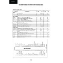
LED FLASHING CODE
IC/Module Name
Slave Address
Bus Error LED Remarks
Ref. No.
Blinking Time
M24C04
A0,A2
2
512x8 EEPROM
IC1002
TDA935x/6x/8x
8A
3
Address of internal TV processor
IC801
VTST6HD64 or
C0
6
PLL Tuner
TU201
CTF551
C0
6
MSP34x5G
80
5
Multistandard Sound Processor
IC3001
PURPOSE: The led indicates the power mode,ocurred I
2
C error and On timer
INPUT:
- Current power mode
- I
- I
2
C Errors
- On timer
Processing:
- If in STANDBY mode and On timer in-active then switch LED off.
- If in STANDBY and On timer active
set LED to blinking, (switch on and off at 1 Hz with a 50 % duty cycle).
- If in POWER-ON mode, switch LED on.
- If an I
- If in STANDBY and On timer active
set LED to blinking, (switch on and off at 1 Hz with a 50 % duty cycle).
- If in POWER-ON mode, switch LED on.
- If an I
2
C error occurred, let the LED blink at 1 Hz, 50 % duty cycle.
For the blinking times see the Table below.
Note:
Only when an I
2
C error occurs for a number of times, or for a number of seconds,
the I
2
the led starts blinking).
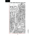
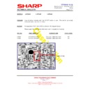
F 7341N0 PRINTED WIRING BOARD. Components side.
0
1
2
3
4
5
6
Y
X
10
1
2
3
4
5
6
7
8
9
Table Error LED blinking times

