Sharp 15FS-25H (serv.man15) Service Manual ▷ View online
15JF-25H
24
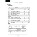
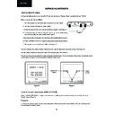
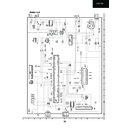
TEA1507 (IC701)
Block Diagram
Block Diagram
th
SUPPLY
MANAGEMENT
internal
supply
UVLO
start
M-level
VCC
1
2
3
GND
S1
CTRL
FREQUENCY
CONTROL
VOLTAGE
CONTROLLED
OSCILLATOR
LOGIC
LOGIC
OVER-
VOLTAGE
PROTECTION
OVERPOWER
PROTECTION
PROTECTION
short
winding
soft
start
S2
OVER-
TEMPERATURE
PROTECTION
S
Q
R
UVLO
Q
MAXIMUM
ON-TIME
PROTECTION
POWER-ON
RESET
−
1
VALLEY
TEA1507
100 mV
clamp
DRIVER
START-UP
CURRENT SOURCE
0.75 V
0.5 V
5
Isense
6
DRIVER
4
DEM
8
DRAIN
7
HVS
n.c.
n.c.
OCP
LEB
blank
Iss
2.5 V
burst
detect
detect
SYMBOL PIN
DESCRIPTION
V
CC
1
supply voltage
GND
2
ground
CTRL
3
control input
DEM
4
input from auxiliary winding for
demagnetization timing, OVP and OPP
demagnetization timing, OVP and OPP
I
sense
5
programmable current sense input
DRIVER
6
gate driver output
HVS
7
high voltage safety spacer, not
connected
connected
DRAIN
8
drain of external MOS switch, input for
start-up current and valley sensing
start-up current and valley sensing
handbook, halfpage
MGU231
TEA1507
1
2
3
4
VCC
GND
CTRL
DEM
DRAIN
HVS
DRIVER
Isense
8
7
6
5
Pin configuration.
25
15JF-25H
AN7523 (IC303)
Block Diagram
Pin Descriptions
Note: Do not apply voltage or current to NC pin from outside
AN5522 (IC501)
Block Diagram
Pin Descriptions
1
2
3
4
5
6
7
8
9
V
CC
Output
GND
Output
Standby
Input
GND
N.C.
V
olume
Pin No.
Pin Name
1
Inverting Input
2
Power Supply
3
Pump-up Output
4
GND
5
Vertical Output
6
Vertical Output Power Supply
7
Non-inverting Input
Pin No.
Description
1
Vcc
2
Ch Output (+)
3
GND
4
Ch Output (-)
5
Stand-by
6
Ch Input
7
GND (Input)
8
N.C
9
Volume
Non-inverting Input
Output Vcc
Output
GND
Pump Up Out
Vcc
Inverting Input
1
2
3
4
5
6
7
Pump Up
Thermal Protection
Amp
+
-
Display

