Sharp XV-Z90E (serv.man10) Service Manual ▷ View online
23
XV-Z90E
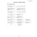
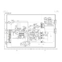
Lamp does not light up.
Yes
Yes
Is the cooling fan rotating?
Check the socket
Is the P1701 (22) pin H level?
No
Check the power circuit or the fan
circuit of the main circuit.
circuit of the main circuit.
Yes
Is the color wheel rotating sound
heard?
heard?
No
Check around IC9101 circuit, motor
driver IC and IC9102, 9003.
driver IC and IC9102, 9003.
No
Normal
Abnormal
Is the lamp discharging sound
heard?
heard?
Yes
Yes
Is DC 340V voltage applied across
the ballast power?
the ballast power?
Lamp failure to light up. Go to
"Formatter Unit Troubleshooting".
"Formatter Unit Troubleshooting".
No
Check the control line P-SAVE.
Is the level converted at IC8001,
B5 output, RN4904?
Is the level converted at IC8001,
B5 output, RN4904?
No
Yes
Check the power circuit.
Yes
Check IC8001 and the
peripheral circuit.
peripheral circuit.
No
Replace the color
wheel.
wheel.
Check the
formatter PWB.
formatter PWB.
No
Replace the lamp.
24
XV-Z90E
No
Yes
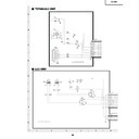
Does POWER LED flicker in red ?
Yes
Turn on the power again.
Yes
Is P1701 (9) pin (P CON0) H?
Is the FAN voltage supplied?
No
Is it in the stand-by due to
an error?
an error?
No
This is the failure of
IC2002.
IC2002.
Yes
FAN_ERROR is being detected.
Check around Q1701 and around
IC2002 (21) pin.
Check around Q1701 and around
IC2002 (21) pin.
Yes
No
No
No
Is 13 V outputted to P1701 (17)
(18) (19) pins?
(18) (19) pins?
Go to "Checking of Power Unit"
Check IC1708, IC1710 and
around these ICs.
around these ICs.
Yes
No
Is BU 5 V outputted from
IC1701?
IC1701?
Yes
Is Bu+6.5V outputted to P1701
(12) (13) (14) pins?
(12) (13) (14) pins?
Check IC1701 and its
periphery."
periphery."
Yes
No
Is BU 3.3 V outputted from
IC1702?
IC1702?
Check IC1702 and its
periphery.
periphery.
Check IC1703 and its
periphery.
periphery.
Yes
No
Is BU 2.5 V outputted from
IC1703?
IC1703?
Check IC8001 and the circuit
around the IC.
around the IC.
Check of IC2002 and around I/O
25
XV-Z90E
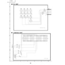
Checking of SOG Circuit
Measure the (7) pin of IC5012
with an oscilloscope.
with an oscilloscope.
This is the failure of the SOG
synchronization separator circuit.
synchronization separator circuit.
Is there the Y signal including sync
signal?
signal?
Measure the (7) pin of IC5010
with an oscilloscope.
with an oscilloscope.
Is the composite synchronized
signal regenerated at proper timing?
signal regenerated at proper timing?
No
Is there output of the (25) pin
of IC3102?
of IC3102?
No
The SOG circuit is normal.
End.
Yes
Yes
Yes
Check around Q5002.
No
Input the S-Video terminal (Y, C)
signal to INPUT 3. Select INPUT 3
with the keys on the main body or
the remote controller.
signal to INPUT 3. Select INPUT 3
with the keys on the main body or
the remote controller.
Is the signal N358?
Does the picture appear?
Is the picture disturbed?
End.
Is the picture signal inputted to the
connector TC (5) (7) pins?
connector TC (5) (7) pins?
Yes
No
No
No
No
Yes
No
In the picture signal inputted to
IC3105 (43) (44) pins?
IC3105 (43) (44) pins?
Yes
Check the input side PWB .
Check IC3505 and the
peripheral circuits of the IC.
peripheral circuits of the IC.
Yes
Yes
Check of the S-Video terminal input.
Check the Y, C signal
lines.
lines.
Check IC3105 and the
peripheral circuits of the
IC.
peripheral circuits of the
IC.
1
Note
Only in case of N358, the noise reduction
function of IC3505 is used and the noise is
reduced, so it is inputted to IC3105 (5), (7).
Only in case of N358, the noise reduction
function of IC3505 is used and the noise is
reduced, so it is inputted to IC3105 (5), (7).
26
XV-Z90E
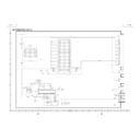
Feed the composite video signal to
INPUT 4. Select INPUT 4 using the
set's key or the remote controller.
INPUT 4. Select INPUT 4 using the
set's key or the remote controller.
Does the picture appear?
Is the picture disturbed?
End.
Is the picture signal inputted to the
connector TC (9) pin?
connector TC (9) pin?
Yes
Yes
No
No
Yes
Check the TERMINAL2 PWB.
No
Is the picture signal inputted to the
(1) pin of IC3105?
(1) pin of IC3105?
Yes
Check the VIDEO-IN signal
line ofIC3502 and IC3503.
line ofIC3502 and IC3503.
No
Is input coming to IC3104 (1) (3) (5)?
Yes
Check IC3102 peripheral circuits.
No
Is output coming from IC3104 (16) (18) (20)?
Yes
Check IC3104 peripheral circuits.
No
Is the picture signal inputted to IC6004 (43) (48) (54)
and the synchronized signal inputted to (30) (31)?
and the synchronized signal inputted to (30) (31)?
Yes
Check around IC3104, IC6001 and IC6002.
No
Is each digital output coming on IC6004 (64) (65) (66) (67)?
Yes
Check IC6004 peripheral circuits.
No
Is output coming from IC8001, DPORT?
Check the formatter PWB.
Yes
Check IC8001 peripheral circuits.
No
Is it N358 signal?
No
Check around IC3501, 3505.
Yes
Is it PAL?
No
Check around IC3504, 3506.
Yes
Is it SECAM?
Check the color system, around IC3105. Others.
No
Check around IC 3105.
Malfunction of the color
system is thinkable.
Malfunction of the color
system is thinkable.
Yes
Checking of Video Input
Check IC3102 peripheral
circuits.
circuits.
1
3
No
Yes
Is synchronized signal
coming to IC3102 (28) (29)
pins?
coming to IC3102 (28) (29)
pins?
2
Note
In case of N358, Y/C separates at IC3505 3 DY/C and inputted
to IC3105 (5) (7) pins.
In case of PAL system, Y/C separates at IC3506 3 Line COM
and inputted to (39) (41) of IC3105.
The video is outputted from (21) (22) (23) at color difference
from IC3105.
In case of N358, Y/C separates at IC3505 3 DY/C and inputted
to IC3105 (5) (7) pins.
In case of PAL system, Y/C separates at IC3506 3 Line COM
and inputted to (39) (41) of IC3105.
The video is outputted from (21) (22) (23) at color difference
from IC3105.

