Sharp XV-Z7000 (serv.man24) Service Manual / Technical Bulletin ▷ View online
LV076
Sharp Electronics (UK) Ltd., Technical Services Group
Model
XV-Z7000E
Problem
The unit does not respond to the remote control signal sent to the front remote control
censor, when it has located at the ceiling-mount. But, the unit works properly after it warms
up. (For example, the unit can not be turned on from the standby mode by the remote
control unit.)
censor, when it has located at the ceiling-mount. But, the unit works properly after it warms
up. (For example, the unit can not be turned on from the standby mode by the remote
control unit.)
Cause
The remote control signal was cancelled due to an influence of external noise which came
into the rear remote control censor.
into the rear remote control censor.
Servicing
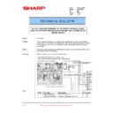
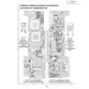
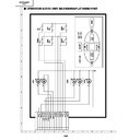
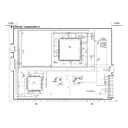
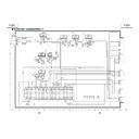
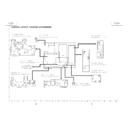
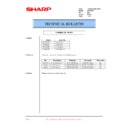
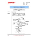
Please modify the unit as shown in the below figure.
• Add a 10k ohms resistor (VRD-RA2BE103J).
• Add a 100 micro-farad capacitor (VCEADA1AW107M).
• Add a 100 micro-farad capacitor (VCEADA1AW107M).
Parts
Ref#
Part Code
Description
Price Code
---
VRD-RA2BE103J
Resistor, 10K ohms
AA
---
VCEADA1AW107M
Capacitor, 100 micro-farad 10V
AC
THE UNIT DOES NOT RESPOND TO THE REMOTE CONTROL SIGNAL
SENT TO THE FRONT SENSOR (WHEN THE UNIT HAS LOCATED AT THE
CEILING-MOUNT)
TECHNICAL BULLETIN
Date:
09 April 2003
Model: XVZ7000E
Ref.:
Ref.:
004
Colour: White
Page:
Page:
1 of 1
Display

